
How a 3 Way Flanged Ball Valve Improves Efficiency in Fluid Flow Management
Industrial piping systems are the arteries of modern manufacturing, chemical processing, and water treatment facilities. When these systems function smoothly, production targets are met, and safety is maintained. However, complex piping routes often require more than just simple on-off control. They need the ability to divert, mix, and manage fluid direction with precision. This is where the 3-way flanged ball valve becomes an indispensable asset.
Managing fluid flow isn't just about moving liquid from point A to point B; it is about control, reliability, and efficiency. Traditional setups might use multiple 2-way valves to achieve a mixing or diverting function, creating a web of potential leak points and complex automation requirements. A single multi-port valve simplifies this architecture significantly.
This guide explores the engineering behind 3-way flanged ball valves. We will look at how they work, the critical specifications you need to know—such as material choices and port configurations—and the best practices for installation and maintenance to ensure your operations run without interruption.
Introduction to 3 Way Flanged Ball Valves
Definition and Purpose
A 3-way ball valve is designed with three ports, typically labeled A, B, and C (or similar). The primary purpose of this design is to allow for one of two operations: diverting flow or mixing flow.
In a diverting application, the valve takes one input and sends it to either of two outputs. For example, you might have a feed line that needs to send water to a storage tank during the day and a treatment facility at night. A simple turn of the handle (or actuation) changes the destination.
In a mixing application, the valve takes two inputs and combines them into a single output. This is frequently used in temperature control systems where hot and cold water are mixed to achieve a specific outlet temperature.
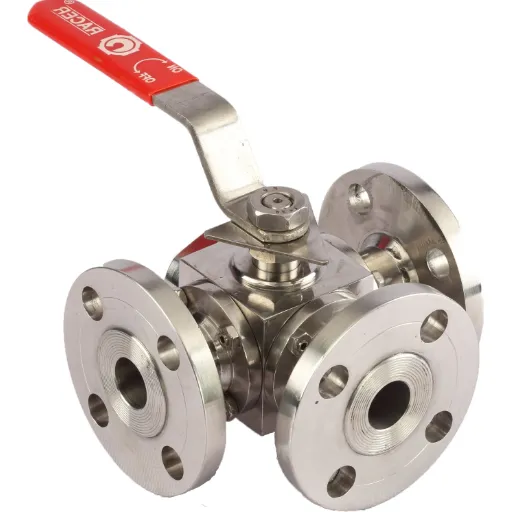
The "flanged" aspect refers to the connection method. Unlike threaded valves that screw into a pipe, flanged valves have a rim (flange) that is bolted to a matching flange on the pipe. This connection style is standard for industrial applications because it is robust, leak-resistant, and allows for easier removal of the valve for maintenance.
Key Features of Flanged Ball Valves
Flanged ball valves are built for rigorous environments. Their design offers several distinct advantages over threaded or welded alternatives:
Robust Connection: The bolted flange connection provides a secure seal that can withstand high pressure and vibration better than threaded connections, which may loosen over time.
Easy Installation and Removal: If a valve needs repair, a flanged connection allows technicians to unbolt the unit and slide it out without cutting the pipe or dismantling the entire system.
Full Port Flow: Many flanged ball valves are "full port," meaning the internal bore is the same diameter as the pipeline. This minimizes pressure drop and ensures high flow rates.
Versatility: They are compatible with a wide range of standard gaskets and bolting patterns (such as ANSI or DIN standards), making them easy to integrate into existing infrastructure.
Importance of Efficient Fluid Flow Management
Efficiency in fluid flow management translates directly to the bottom line. Every time a fluid changes direction, passes through a valve, or encounters friction, energy is lost. This energy loss manifests as pressure drops, requiring pumps to work harder and consume more electricity.
Using a single 3-way valve instead of two or three 2-way valves reduces the friction losses associated with multiple fittings and bends. Furthermore, it simplifies the control logic. Managing one actuator is far simpler and less prone to error than synchronizing multiple actuators to open and close in a specific sequence. Efficient flow management also reduces the risk of water hammer and system shock, protecting expensive pumps and instrumentation downstream.
Specifications of 3 Way Flanged Ball Valves
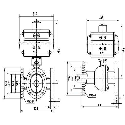
Dimensions and Sizes: Understanding the 2 Inch Standard
While these valves come in sizes ranging from half an inch to over 12 inches, the 2-inch 3-way flanged ball valve holds a unique position in the industry. It is often considered the "standard" size for medium-duty industrial applications.
The 2-inch diameter strikes a balance. It provides significantly more flow capacity than typical residential plumbing (often 1 inch or less) but remains compact enough to be easily handled and installed by a minimal crew without heavy lifting equipment. In many chemical processing skids and water filtration units, the 2-inch piping is the default for main distribution lines.
When specifying dimensions, pay close attention to the "face-to-face" dimension. This is the length of the valve from one flange face to the other. Different manufacturers may follow different standards (like ANSI B16.10), so verifying this measurement is critical to ensuring the new valve will fit into the gap left by the old one.
Material Options: Stainless Steel vs. Other Materials
The longevity of a valve is dictated by its material. If the fluid is corrosive or abrasive, the wrong material will lead to premature failure.
Stainless Steel (304 and 316):
Stainless steel is the gold standard for many industries. Grade 316 stainless steel, in particular, offers excellent corrosion resistance thanks to the addition of molybdenum. It is the preferred choice for chemical processing, food and beverage production, and marine environments. Stainless steel valves are durable, handle high temperatures well, and resist rust, ensuring the valve remains operational for years.
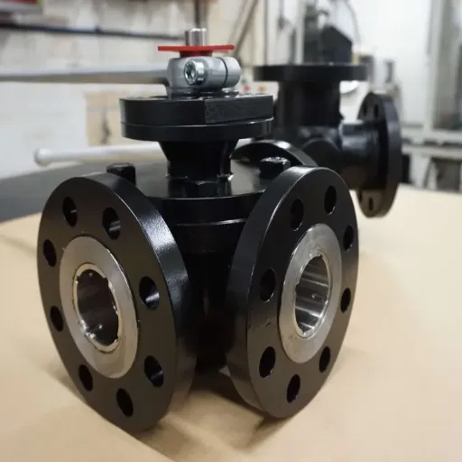
Carbon Steel:
Carbon steel is stronger and often more affordable than stainless steel. It is commonly used in high-pressure oil and gas applications where corrosion is controlled through other means or isn't the primary concern. However, it is susceptible to rusting if exposed to moisture without protection.
Brass and Bronze:
These are typically found in lower-pressure water and gas applications. They are cost-effective but generally not suitable for harsh chemicals or high temperatures.
PVC and CPVC:
For highly corrosive acids at low temperatures and pressures, plastic valves are an option. They are lightweight and immune to rust but lack the structural strength and temperature tolerance of metal flanged valves.
Port Configurations and Their Applications
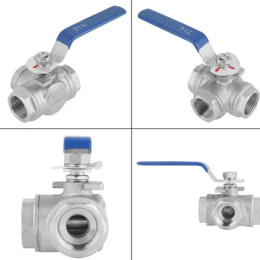
The "heart" of a 3-way valve is the shape of the port cut into the ball. There are two primary configurations: L-Port and T-Port. Understanding the difference is crucial as they perform different functions.
L-Port (Diverting Valve):
The L-Port design has a bore drilled through the ball in the shape of an "L". This allows flow to be directed from the center port to either side port, but generally not to both simultaneously.
Application: Switching a pipeline from Tank A to Tank B. It is a true diverter. It allows you to select one outlet or the other, or shut off flow completely (depending on the handle rotation range).
T-Port (Mixing or Diverting Valve):
The T-Port design has a bore in the shape of a "T". It can do everything an L-Port can do, plus more. It can connect all three ports simultaneously.
Application: This allows for mixing streams A and B into stream C. It can also allow for straight-through flow while diverting a portion to the third port. It offers greater flexibility but requires careful attention to the handle position to ensure the flow is going where intended.
Benefits of Using Flanged 3-Way Ball Valves
Enhanced Control in Fluid Flow Systems
Precision is paramount in modern industry. A 3-way flanged ball valve acts as a central control hub. In a cooling loop, for instance, a temperature sensor can govern an actuator on the valve. If the equipment gets too hot, the valve modulates to send more fluid through a heat exchanger. If the temperature is stable, it bypasses the exchanger to save energy.
This level of control allows for automated, dynamic responses to changing process conditions. Because ball valves are "quarter-turn" valves (moving from closed to open in 90 degrees), they respond quickly. This rapid response time is superior to multi-turn valves like gate or globe valves, which take longer to actuate and can lead to lags in process control.
Reduced Maintenance Costs and Increased Reliability
Every connection point in a pipe is a potential leak path. By replacing a tee fitting and two isolation valves with a single 3-way valve, you eliminate several flange connections and gaskets. Fewer gaskets mean fewer potential leaks and less maintenance monitoring.
Furthermore, the ball valve design itself is low maintenance. The spherical ball floats slightly between two seats. As fluid pressure pushes against the ball, it presses tighter against the downstream seat, creating a positive seal. This self-sealing characteristic means that ball valves often remain leak-tight even after thousands of cycles.
Flanged valves specifically reduce maintenance downtime. In the event of a seat failure, maintenance crews can unbolt the valve body, lift it out, repair or replace it, and bolt it back in. There is no need for welding torches or pipe cutters, which would require "hot work" permits and longer shutdowns.
Automation Capabilities for Improved Efficiency
3-way flanged ball valves are ideal candidates for automation. Most modern flanged valves come with an ISO 5211 mounting pad—a standardized platform on top of the valve stem designed to accept actuators.
You can easily mount:
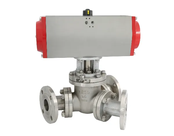
Pneumatic Actuators: Powered by compressed air, these are fast-acting and safe for hazardous environments where electricity might pose a spark risk.
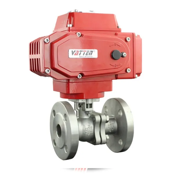
Electric Actuators: These offer precise positioning and can be easily integrated into digital control systems (PLC or SCADA).
Automating these valves removes the variable of human error. An operator might accidentally turn a manual valve to the wrong position or leave it partially open. An automated system performs the exact same operation every time, ensuring consistent product quality and safety.
Installation and Maintenance Considerations
Proper End Connections for Flanged Ball Valves
Installation begins with the flanges. Ensure that the flanges on your pipe match the standard of the valve (e.g., ANSI Class 150 or PN16). Mismatched flanges will not seal and can damage the valve body.
When bolting the valve into the line:
Alignment: The pipe flanges must be parallel and concentric. Forcing a valve into misaligned pipes introduces stress that can crack the valve body or cause the stem to bind.
Gaskets: Always use new gaskets compatible with the fluid media. Never reuse old gaskets.
Torque Sequence: Tighten the bolts in a star or cross pattern. Do not fully tighten one bolt before moving to the next. Gradually increase the torque on all bolts to ensure the gasket is compressed evenly. Uneven compression is a leading cause of flange leaks.
Regular Maintenance Practices to Ensure Longevity
While ball valves are robust, they are not immune to wear. A preventive maintenance schedule should be established based on the severity of the service.
Cycling: If a valve sits in one position for months, the seats can stick to the ball. "Exercise" the valve by cycling it partially or fully on a regular basis (e.g., once a month) to keep the movement smooth.
Stem Seal Inspection: The most common leak point on a ball valve is the stem packing (where the handle shaft enters the body). Check this area regularly. Most valves have an adjustable packing nut that can be tightened slightly to stop minor leaks.
Lubrication: Some valves have grease fittings. If yours does, ensure it is lubricated according to the manufacturer's recommendations.
Common Issues and Troubleshooting Tips
Despite best efforts, issues can arise. Here are common problems and how to address them:
Leaking Through the Valve (Passing): This occurs when the valve is closed (or diverted), but fluid still trickles past the ball. This is usually caused by damaged seats. Debris in the line can scratch the soft PTFE seats. The solution is usually to install a repair kit with new seats and seals.
Leaking at the Flange: This suggests a gasket failure or loose bolts. Check the torque on the bolts first. If that fails, the line must be depressurized to replace the gasket.
Hard to Turn: If the valve is difficult to actuate, it may be due to thermal expansion trapped in the body cavity or simply a buildup of process material (scaling) inside the valve. In some cases, the stem packing is overtightened. Loosen the packing nut slightly to see if torque decreases, but ensure it doesn't leak.
Recently Posted
-
Understanding the Functions of Suction Valve and Discharge Valve in Pump Systems
December 18, 2025Industrial pump systems rely on precise mechanical coordination to transport fluids effectively. At the heart of this process are Read More
 -
Exploring Advanced Technologies in Air Compressor Discharge Valve Manufacturing
December 17, 2025The efficiency of any pneumatic system relies heavily on the performance of its smallest components. Among these, the air compress Read More
 -
Exploring Different Discharge Valve Types for Efficient Fluid Flow Management
December 16, 2025Industrial systems rely heavily on precision components to maintain safety, efficiency, and operational integrity. Among these com Read More
 -
How the Discharge Valve AC Affects Performance and Longevity of Cooling Systems
December 15, 2025The efficiency of any air conditioning system relies heavily on the precise coordination of its internal components. While the com Read More

Contact Us
Recommended Products
-
 DN1000 Insertion Type Ultrasonic Flow Meter for Clean Water Pure WaterNegotiableMOQ: 100 Sets
 -
Advanced Electromagnetic Flowmeter With Integrated Liquid Measurement TechnologyNegotiableMOQ: 10 Units
-
High Precision Electromagnetic Flow Meter for Southeast Asia Export - Easy Installation & Reliable After-SaleNegotiableMOQ: 10 Units
-
Advanced Digital Vortex Flow Meter for Accurate Water and Liquid MeasurementNegotiableMOQ: 10 Pieces
-
DN50 304 Stainless Steel Turbine Flowmeter for Diesel Oil MeasurementNegotiableMOQ: 10 Units
-
Low-Temperature Turbine Flowmeter for Liquid Nitrogen Applications in Cryogenic SystemsNegotiableMOQ: 10 Units
-
Industrial UV Disinfection Machine for Food & Beverage Industry - UVTunnelTM Tech, 1-40℃ Working TempNegotiableMOQ: 1 Set
-
C 7635 High-purity Water Conductivity Transmitter With Automatic Temperature Compensation 0-100°CNegotiableMOQ: 1 Set
-
C 3655 Conductivity Meter Output Conductivity Transmitter With IP65 Waterproof HousingNegotiableMOQ: 1 Set
-
High Performance Electric Regulating Valve for Environmental Protection Water Treatment SystemsNegotiableMOQ: 1 Piece

-
High Quality Pneumatic Control Valve for Chemical Pharmaceutical Industry Chinese Strong Factory With Spot StockNegotiableMOQ: 1 Piece
-
Pneumatic or Electric Actuator Compatible Full Fluorine-Lined Butterfly Valve With On/Off and Smart Regulating OptionsNegotiableMOQ: 1 Set
-
Powder Conveying Specialized Pneumatic Y-Type Ball Valve, Full Bore Design With No Dead Space for Clean MediaNegotiableMOQ: 1 Set
-
Manual, Pneumatic, or Electric Flanged Ball Valve With ISO5211 High Platform, Easy 90-Degree Operation for Fluid ControlNegotiableMOQ: 1 Set
-
Zero Leakage Full Fluorine-Lined Butterfly Valve Featuring Superior Corrosion Resistance and Long Service LifeNegotiableMOQ: 1 Set
-
Bottom Discharge Valve VTF-88-3 Series, DN25-DN300, Stainless Steel 316L/Carbon Steel, PN10/PN16 Class 150, Manual or Pneumatic ActuationNegotiableMOQ: 1 Set
-
Cost-Effective Knife Gate Valve With Rigid/Elastic Gate Options - Ensures Tight Shutoff and High Performance in Diverse Industrial SettingsNegotiableMOQ: 1 Set
-
FLS PH/ORP 200 Epoxy Resin Body Glass Bulb Electrode (Single-Junction/Double-Junction Versions)NegotiableMOQ: 100 Pieces
-
FLS F3.20 Flow Sensor Optimized for HVAC Systems, Cooling Units, and Boiler Feed Water, Featuring Low Maintenance and High Precision AccuracyNegotiableMOQ: 100 Pieces
-
FLS F3.80 Oval Gear Flow Sensor – High Precision for High-Viscosity Liquids (10-150L/h, IP65)NegotiableMOQ: 100 Pieces