
Exploring Advanced Technologies in Air Compressor Discharge Valve Manufacturing
The efficiency of any pneumatic system relies heavily on the performance of its smallest components. Among these, the air compressor discharge valve plays a pivotal role in regulating airflow, maintaining system pressure, and ensuring operational safety. While often overlooked, this component dictates the thermodynamic efficiency of the compression cycle and the longevity of the entire compressor unit.
In industrial settings, valve failure can lead to catastrophic downtime, energy wastage, and safety hazards. Consequently, the engineering behind these valves has evolved significantly. Modern manufacturing utilizes advanced materials, precision machining, and rigorous quality control to produce valves capable of withstanding high temperatures, rapid cycling, and corrosive environments.
This article examines the technical intricacies of air compressor discharge valves. We will explore their fundamental role within the compression system, the key components that ensure their functionality, and the cutting-edge manufacturing technologies driving the industry forward. Furthermore, we provide a technical guide on troubleshooting and maintenance to maximize equipment lifecycle.
Understanding the Role of Discharge Valves in Air Compressors
What is a Discharge Valve?
A discharge valve is a pressure-activated mechanical device located at the discharge port of a compressor cylinder or airend. It opens automatically when the pressure inside the cylinder exceeds the pressure in the discharge line (plus the valve spring force) and closes immediately as the piston or rotor begins the intake phase.
Unlike mechanically actuated valves found in internal combustion engines, compressor valves operate solely on pressure differentials. This "automatic" operation requires precise engineering to ensure the valve opens at the exact moment required to minimize energy losses. If a valve opens too late, the compressor consumes excess power to over-pressurize the gas (over-compression). If it leaks or closes too late, compressed gas re-expands into the cylinder (re-expansion), significantly reducing volumetric efficiency.
Importance of Discharge Valves in Compressor Systems
Why are discharge valves considered critical to compressor health? The discharge valve directly influences the thermodynamic efficiency of the machine. A well-designed valve minimizes flow resistance (pressure drop) as the gas exits the cylinder. High resistance results in increased power consumption and higher discharge temperatures, which can degrade lubricants and shorten the life of seals and rings.
Furthermore, the discharge valve must withstand extreme operating conditions. In a reciprocating compressor running at 1000 RPM, the valve opens and closes 1000 times per minute. Over a year of continuous operation, this amounts to over 500 million cycles. The valve must endure this fatigue while exposed to high temperatures and potentially corrosive condensates without fracturing or deforming.
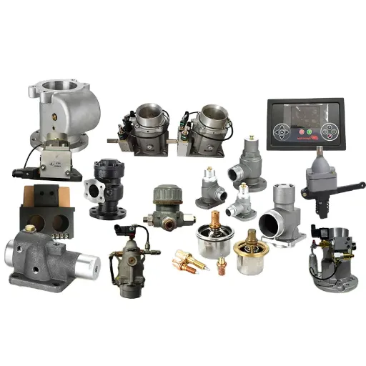
Types of Discharge Valves Used in Air Compressors
Manufacturers utilize various valve designs depending on the compressor type, pressure range, and application.
Reed Valves: Common in smaller reciprocating compressors, these consist of thin, flexible metal strips that flap open and closed. They are simple and cost-effective but limited in flow capacity.
Plate Valves: Used in industrial reciprocating compressors, these feature concentric steel rings or plates held against a seat by springs. They offer high durability and large flow areas.
Poppet Valves: These utilize mushroom-shaped sealing elements and are often found in high-pressure applications due to their robust sealing capabilities and aerodynamic flow paths.
Channel Valves: These use channel-shaped elements and leaf springs, providing a cushioned opening that reduces impact stress, suitable for heavy-duty applications.
Key Components of Air Compressor Valves
Overview of Air Compressor Check Valves
What is the difference between a discharge valve and a check valve? While both prevent backflow, they serve different locations and purposes. The discharge valve is internal, located on the cylinder head, managing the compression cycle. The check valve is typically external, located in the discharge line between the compressor head and the receiver tank.
The check valve prevents compressed air in the tank from flowing back into the compressor head when the unit shuts off. Without a functional check valve, the compressor would attempt to start against "head pressure," causing motor stall or burnout. These valves usually employ a spring-loaded poppet or a swing mechanism and must provide a bubble-tight seal to maintain system pressure during idle periods.
Pressure Relief Valves and Their Functionality
Safety in pneumatic systems is non-negotiable. Pressure relief valves (PRVs), or safety valves, are mechanical devices designed to protect the system from over-pressurization.
How does a pressure relief valve function? The PRV is set to a specific "cracking pressure," usually slightly above the system's maximum operating pressure. A spring holds a disc or poppet against a seat. If system pressure exceeds the spring force, the valve pops open, venting excess air to the atmosphere until safe pressure is restored.
These valves are critical safety devices, not regulation devices. They are the final line of defense against catastrophic vessel failure or motor overload. In discharge valve manufacturing and system design, the PRV sizing must account for the compressor's maximum flow rate to ensure it can vent pressure faster than the compressor can build it.
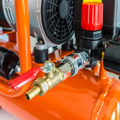
Comparing Ball Valves and Brass Valves in Compressor Applications
In the discharge piping network, isolation valves are necessary for maintenance and system configuration. Two common terms often arise: ball valves and brass valves.
Ball Valves: This refers to the mechanism. A ball valve uses a spherical closure unit with a central hole. A quarter-turn allows for quick, unobstructed flow or complete shut-off. In compressor discharge lines, full-port ball valves are preferred because they create negligible pressure drop when open.
Brass Valves: This refers to the material. Brass is a common alloy for general-purpose pneumatic valves due to its corrosion resistance and machinability.
Most isolation valves in standard air compressor setups are brass ball valves. The brass body offers sufficient strength for standard pressures (up to 300-600 PSI), while the ball mechanism provides the reliability and low flow resistance required for discharge lines. However, for oil-free or high-temperature industrial discharge lines, stainless steel valves may be preferred over brass to prevent material degradation or contamination.
Manufacturing Technologies for Air Compressor Discharge Valves
Materials Used in Discharge Valve Production
Material selection dictates the valve's fatigue limit and resistance to environmental stressors.
Stainless Steel (400 Series): The standard for valve plates and reeds. Grades like 410 or 420 stainless steel are heat-treated to achieve high hardness and excellent fatigue strength, essential for surviving millions of impact cycles.
PEEK (Polyether Ether Ketone): In modern high-performance compressors, thermoplastic polymers like PEEK are increasingly used for valve plates. PEEK offers exceptional impact resistance, high thermal stability, and corrosion resistance. Its lower mass compared to steel reduces inertia, allowing for faster valve response times and improved efficiency.
Carbon Steel: Used for valve seats and guards, often subjected to hardening processes like carburizing or nitriding to prevent wear from the constant impact of the valve plate.
Innovations in Valve Manufacturing Processes
How are these components manufactured to such high tolerances? Advanced manufacturing techniques are employed to ensure flatness and surface finish, which are critical for sealing.
Laser Cutting and Fine Blanking: For reed and plate valves, traditional stamping can introduce micro-cracks along the edges, serving as initiation points for fatigue failure. Fine blanking and precision laser cutting produce clean, stress-free edges, significantly extending component life.
Precision Lapping and Grinding: Valve seats and plates must be perfectly flat to seal high-pressure gas. Double-disk grinding and lapping processes achieve flatness measured in light bands (helium light bands), ensuring a leak-free seal between the plate and the seat.
Stress Relieving: After machining, valve components often undergo shot peening or tumbling. This process introduces compressive residual stresses on the surface, which helps inhibit the propagation of fatigue cracks during operation.
Quality Control Measures in Valve Production
Reliability is engineered through rigorous testing. Quality control in valve manufacturing goes beyond dimensional checks.
Flatness Verification: Optical flats and monochromatic light sources are used to verify surface flatness to within micrometers.
Leak Testing: Assembled valves undergo static leak testing to ensure the seal integrity between the plate and seat.
Fatigue Testing: Manufacturers conduct accelerated life testing, simulating the compressor's operating environment to verify that the steel or polymer batches meet the required cycle life without failure.
Troubleshooting Common Issues with Air Compressor Valves
Identifying Signs of Valve Failure
Early detection of discharge valve failure can save the cylinder walls and piston rings. Look for these distinct indicators:
High Discharge Temperature: If a discharge valve leaks, hot compressed gas flows back into the cylinder and is re-compressed. This causes a rapid spike in discharge air temperature.
Extended Cycle Times: A leaking valve reduces the volumetric efficiency. The compressor will take longer to build pressure in the receiver tank or may fail to reach cut-out pressure entirely.
Unusual Noise: A broken valve plate or spring often creates a distinct clicking, clattering, or humming noise synchronized with the compressor stroke.
Tank Pressure in Cylinder: On a reciprocating compressor, if you can rotate the flywheel by hand and feel resistance immediately (without the intake stroke), the discharge valve may be leaking tank pressure back into the cylinder (assuming the check valve is also failing or absent).
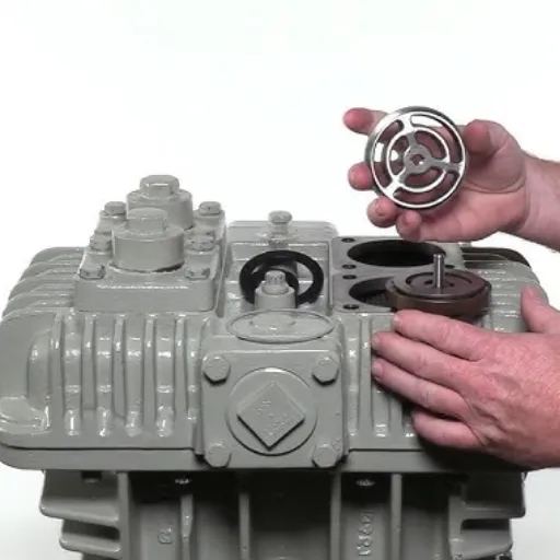
Steps for Repairing or Replacing Discharge Valves
When a valve failure is confirmed, prompt repair is necessary.
Isolation and Depressurization: Always disconnect power and fully vent the system pressure. Confirm zero pressure in both the tank and the cylinder head.
Disassembly: Remove the cylinder head bolts. Carefully separate the head from the cylinder block, preserving the gasket if possible (though replacement is recommended).
Inspection: examine the valve plate assembly. Look for carbon buildup, broken reeds, or pitted valve seats. Carbon deposits are a common cause of valve leakage and can often be cleaned.
Lapping or Replacement: If the seats are slightly worn, they can sometimes be lapped on a surface plate with abrasive compound to restore flatness. However, if plates are cracked or springs are fatigued, the entire valve assembly or kit should be replaced.
Reassembly: Install new gaskets and torque the cylinder head bolts to the manufacturer's specifications in a star pattern to ensure even clamping force.
Preventative Maintenance Tips for Longevity
Maximizing valve life requires a proactive approach to maintenance.
Air Filtration: Intake air usually contains abrasive dust. A clogged or missing intake filter allows particulates to enter the cylinder, which acts as a lapping compound, rapidly wearing down valve sealing surfaces.
Oil Maintenance: In lubricated compressors, oil carbonization is the enemy. Degraded oil forms sticky varnish and hard carbon deposits on valves, preventing them from seating or cooling properly. Adhere strictly to oil change intervals and use high-quality synthetic lubricants designed for high temperatures.
Duty Cycle Management: Valves suffer most during start-up and shut-down transients. Short-cycling the compressor accelerates wear. Ensure the receiver tank is sized correctly to maintain manageable cycle times.
Recently Posted
-
Understanding the Functions of Suction Valve and Discharge Valve in Pump Systems
December 18, 2025Industrial pump systems rely on precise mechanical coordination to transport fluids effectively. At the heart of this process are Read More
 -
Exploring Different Discharge Valve Types for Efficient Fluid Flow Management
December 16, 2025Industrial systems rely heavily on precision components to maintain safety, efficiency, and operational integrity. Among these com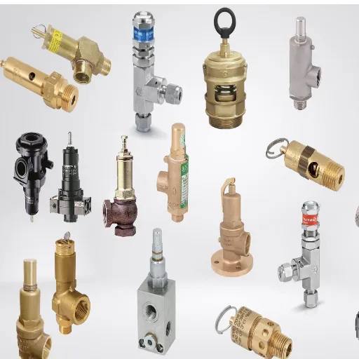 Read More
 -
How the Discharge Valve AC Affects Performance and Longevity of Cooling Systems
December 15, 2025The efficiency of any air conditioning system relies heavily on the precise coordination of its internal components. While the com Read More
 -
Understanding the Discharge Valve Function in Industrial Pumping Systems and Applications
December 15, 2025In the complex ecosystem of industrial fluid dynamics, the stability and efficiency of a system often hinge on the performance of Read More

Contact Us
Recommended Products
-
 DN1000 Insertion Type Ultrasonic Flow Meter for Clean Water Pure WaterNegotiableMOQ: 100 Sets
 -
Advanced Electromagnetic Flowmeter With Integrated Liquid Measurement TechnologyNegotiableMOQ: 10 Units
-
High Precision Electromagnetic Flow Meter for Southeast Asia Export - Easy Installation & Reliable After-SaleNegotiableMOQ: 10 Units
-
Advanced Digital Vortex Flow Meter for Accurate Water and Liquid MeasurementNegotiableMOQ: 10 Pieces
-
DN50 304 Stainless Steel Turbine Flowmeter for Diesel Oil MeasurementNegotiableMOQ: 10 Units
-
Low-Temperature Turbine Flowmeter for Liquid Nitrogen Applications in Cryogenic SystemsNegotiableMOQ: 10 Units
-
Industrial UV Disinfection Machine for Food & Beverage Industry - UVTunnelTM Tech, 1-40℃ Working TempNegotiableMOQ: 1 Set
-
C 7635 High-purity Water Conductivity Transmitter With Automatic Temperature Compensation 0-100°CNegotiableMOQ: 1 Set
-
C 3655 Conductivity Meter Output Conductivity Transmitter With IP65 Waterproof HousingNegotiableMOQ: 1 Set
-
High Performance Electric Regulating Valve for Environmental Protection Water Treatment SystemsNegotiableMOQ: 1 Piece


-
High Quality Pneumatic Control Valve for Chemical Pharmaceutical Industry Chinese Strong Factory With Spot StockNegotiableMOQ: 1 Piece
-
Pneumatic or Electric Actuator Compatible Full Fluorine-Lined Butterfly Valve With On/Off and Smart Regulating OptionsNegotiableMOQ: 1 Set
-
Powder Conveying Specialized Pneumatic Y-Type Ball Valve, Full Bore Design With No Dead Space for Clean MediaNegotiableMOQ: 1 Set
-
Manual, Pneumatic, or Electric Flanged Ball Valve With ISO5211 High Platform, Easy 90-Degree Operation for Fluid ControlNegotiableMOQ: 1 Set
-
Zero Leakage Full Fluorine-Lined Butterfly Valve Featuring Superior Corrosion Resistance and Long Service LifeNegotiableMOQ: 1 Set
-
Bottom Discharge Valve VTF-88-3 Series, DN25-DN300, Stainless Steel 316L/Carbon Steel, PN10/PN16 Class 150, Manual or Pneumatic ActuationNegotiableMOQ: 1 Set
-
Cost-Effective Knife Gate Valve With Rigid/Elastic Gate Options - Ensures Tight Shutoff and High Performance in Diverse Industrial SettingsNegotiableMOQ: 1 Set
-
FLS PH/ORP 200 Epoxy Resin Body Glass Bulb Electrode (Single-Junction/Double-Junction Versions)NegotiableMOQ: 100 Pieces
-
FLS F3.20 Flow Sensor Optimized for HVAC Systems, Cooling Units, and Boiler Feed Water, Featuring Low Maintenance and High Precision AccuracyNegotiableMOQ: 100 Pieces
-
FLS F3.80 Oval Gear Flow Sensor – High Precision for High-Viscosity Liquids (10-150L/h, IP65)NegotiableMOQ: 100 Pieces