
Control Valve Hydraulic Systems Explained: A Guide to Their Functionality and Efficiency
Hydraulic systems are the unseen force behind much of the modern world's heavy machinery, from construction equipment to agricultural tractors. At the heart of these powerful systems lies a critical component: the hydraulic control valve. Understanding how these valves function is key to ensuring the efficiency, safety, and reliability of any hydraulic application.
This guide provides a comprehensive overview of hydraulic control valves. We will explore what they are, the different types available, and their essential components. You will learn the basic principles of how hydraulic systems operate, the specific role of spools and flow rate, and the differences between various directional control valves. Finally, we will cover best practices for maintenance, troubleshooting common issues, and strategies for improving overall system efficiency. This information will help you optimize the performance and extend the lifespan of your hydraulic equipment.
Understanding Hydraulic Control Valves
What is a Hydraulic Control Valve?
A hydraulic control valve is a mechanical device used to regulate the flow, pressure, and direction of hydraulic fluid. By controlling these variables, the valve directs the power of the hydraulic system to perform specific tasks, such as moving a cylinder, rotating a motor, or lifting a heavy load. Think of it as the brain of the hydraulic circuit, making decisions that translate fluid power into controlled mechanical motion. Without these valves, the immense force generated by hydraulic fluid would be unmanageable and chaotic.
Types of Hydraulic Control Valves
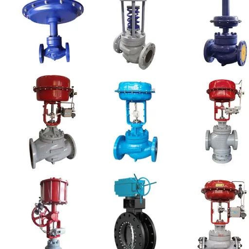
Hydraulic control valves are categorized based on their primary function. The three main types are:
Directional Control Valves: These valves are responsible for starting, stopping, and changing the direction of fluid flow. They ensure the hydraulic fluid travels to the correct component at the right time, enabling the movement of actuators like cylinders and motors.
Pressure Control Valves: As their name suggests, these valves regulate the pressure within a hydraulic system. They protect the system from over-pressurization, which could damage components or create safety hazards. Common examples include relief valves, pressure-reducing valves, and sequence valves.
Flow Control Valves: These valves manage the speed of hydraulic actuators by controlling the volume of fluid that passes through a specific part of the circuit per unit of time. By adjusting the flow rate, an operator can control the speed of a hydraulic cylinder's extension or the rotational speed of a hydraulic motor.
Components of a Control Valve System
A typical control valve is an assembly of several key parts working in unison. While designs vary, most hydraulic control valves include the following components:
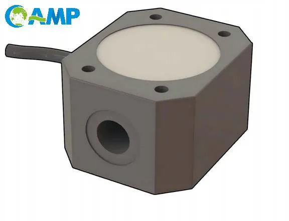
Valve Body: This is the main housing that contains all the internal parts. It has ports for the fluid to enter and exit, connecting the valve to the rest of the hydraulic system.
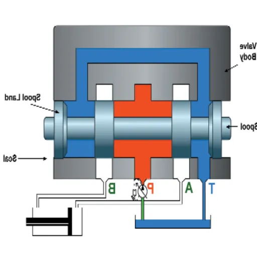
Spool: The spool is a cylindrical component that slides or rotates inside the valve body. It has lands (wider sections) and grooves (narrower sections) that block or open pathways for the fluid to flow through. The position of the spool determines the path of the hydraulic fluid.
Actuator (Lever, Solenoid, etc.): This is the mechanism used to move the spool. Actuators can be manual (like a lever or pedal), electric (solenoids), hydraulic (pilot pressure), or pneumatic.
Springs: Springs are often used to return the spool to a neutral or default position when the actuator is not engaged. This ensures the system returns to a safe or resting state.
How Hydraulic Systems Operate
Basic Principles of Hydraulic Systems
Hydraulic systems operate based on Pascal's Law, which states that pressure applied to a confined, incompressible fluid is transmitted equally in all directions throughout the fluid. In a simple hydraulic system, a pump generates flow, which is then restricted, creating pressure. This pressurized fluid is directed by control valves to an actuator, such as a hydraulic cylinder.
The force generated is a product of the pressure and the surface area it acts upon (Force = Pressure × Area). This principle allows hydraulic systems to multiply force, enabling a small input force to generate a much larger output force, which is why they are ideal for heavy-duty applications.
The Role of Spools in Hydraulic Control
The spool is the central moving part within a directional control valve. Its movement is what directs the flow of hydraulic fluid. When an operator activates the valve (for example, by moving a lever), the spool slides within the valve body. The lands on the spool block certain passages while the grooves open others.
This action connects the pump port to one of the work ports (leading to an actuator) and the other work port to the tank (reservoir) port. This allows pressurized fluid to extend a cylinder, for instance, while the fluid on the other side of the cylinder's piston returns to the tank. When the spool is moved to another position, the connections change, reversing the actuator's movement. In a neutral position, the spool might block all ports or allow fluid to circulate back to the tank, depending on the design.
Flow Rate and its Importance in Hydraulic Systems
Flow rate, typically measured in gallons per minute (GPM) or liters per minute (LPM), determines the speed of the hydraulic actuators. A higher flow rate will cause a cylinder to extend or retract faster, and a motor to rotate more quickly.
Flow control valves are used to precisely manage this speed. They work by creating a restriction in the flow path. Some are simple needle valves that can be manually adjusted, while others are pressure-compensated, meaning they maintain a constant flow rate even if the system pressure changes. Proper control of flow rate is crucial for the smooth and predictable operation of hydraulic machinery.
Directional Control Valves
Introduction to Directional Control Valves
Directional control valves manage the path of fluid flow. Their primary function is to direct pressurized oil to one side of an actuator while allowing the oil from the other side to return to the reservoir. They are classified by the number of ports, the number of spool positions, the actuation method, and the type of spool.
For example, a "4/3 valve" is a common designation. The "4" indicates it has four ports (Pump, Tank, and two work ports, A and B), and the "3" indicates it has three positions (e.g., extend, retract, and neutral).
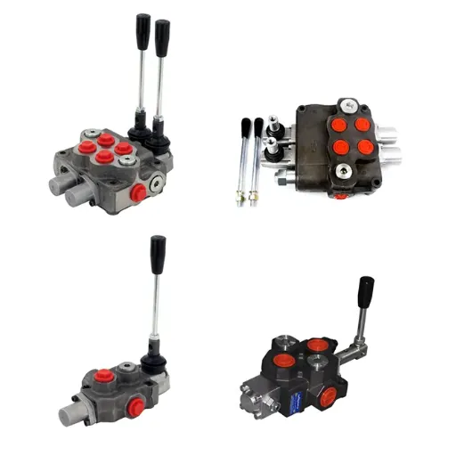
2 Spool vs. 1 Spool Directional Valves
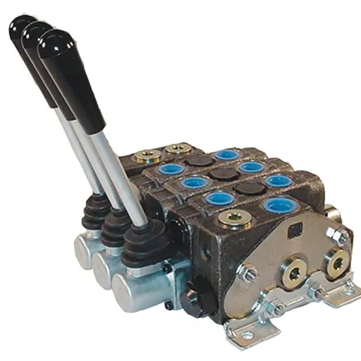
In many hydraulic systems, especially on mobile equipment like excavators and loaders, multiple functions need to be controlled independently. Instead of using several individual valves, manufacturers often use a monoblock or sectional valve body that contains multiple spools.
1 Spool Directional Valve: A single-spool valve controls one hydraulic circuit. It will have one actuator (like a lever) to move its single spool, controlling a single function, such as lifting the arm of a loader.
2 Spool Directional Valve: A two-spool valve contains two spools within a single valve body. This allows an operator to control two separate hydraulic functions with two separate levers. For example, on a tractor with a front-end loader, one spool might control the lift arms, while the second spool controls the bucket tilt. This integrated design is more compact and often simpler to plumb than using two separate single-spool valves.
Valves can have many more spools, with 6-spool or even more complex configurations being common on advanced machinery.
Choosing the Right Directional Control Valve
Selecting the appropriate directional control valve requires considering several factors:
Flow Rate (GPM): The valve must be rated to handle the maximum flow rate produced by the system's pump. An undersized valve will create a pressure drop, generate heat, and reduce system efficiency.
Maximum Pressure: The valve body and its components must be able to withstand the maximum operating pressure of the system.
Number of Spools: This depends on how many independent functions need to be controlled.
Actuation Method: Will the valve be operated manually with a lever, electronically with solenoids for remote control, or with hydraulic pilot pressure?
Spool Center Condition: What should happen when the valve is in the neutral position? An "open center" spool allows the pump flow to return directly to the tank, which is common in simple systems. A "closed center" spool blocks all ports, used in more complex systems with variable displacement pumps.
Efficiency and Maintenance of Hydraulic Control Valves
Maintaining Hydraulic Control Valves for Optimal Performance
Routine maintenance is the best way to prevent issues with hydraulic control valves. Key practices include:
Keep Hydraulic Fluid Clean: Contamination is the number one enemy of hydraulic systems. Dirt, metal particles, and water can cause spools to stick, wear out seals, and clog small orifices. Use high-quality filters and change them regularly according to the manufacturer's recommendations.
Monitor Fluid Temperature: Excessive heat degrades hydraulic fluid and can damage seals. Ensure the system has adequate cooling and that the fluid operates within its specified temperature range.
Regular Inspections: Visually inspect valves for external leaks, which can indicate failing seals or loose fittings. Listen for unusual noises, which might suggest cavitation or internal leakage. Check that actuators (levers, solenoids) are functioning correctly.
Follow Service Intervals: Adhere to the maintenance schedule provided by the equipment manufacturer for fluid and filter changes.
Common Issues and Troubleshooting Tips
Even with proper maintenance, problems can arise. Here are some common issues and how to troubleshoot them:
Sticking Spool: If a valve is slow to respond or gets stuck in one position, the cause is often contamination or varnish buildup on the spool. Sometimes, this can be resolved by flushing the system. In more severe cases, the valve may need to be disassembled and cleaned.
Internal or External Leaks: External leaks are usually caused by worn-out O-rings or seals. Internal leakage occurs when fluid bypasses the spool, reducing system efficiency and causing actuators to drift. This is typically due to wear on the spool or valve body and may require replacing the valve.
Solenoid Failure: If an electrically actuated valve fails to shift, the problem could be the solenoid. Check for power at the solenoid connector. If power is present but the solenoid doesn't activate (you should hear a click), the coil may have failed and needs to be replaced.
Improving Efficiency in Hydraulic Systems
Beyond basic maintenance, there are several ways to improve the overall efficiency of a hydraulic system:
Use Correct Fluid Viscosity: Using a hydraulic fluid with the correct viscosity for your operating temperature range minimizes internal leakage and reduces the energy required to pump the fluid.
Minimize Pressure Drops: Ensure hoses and tubing are properly sized for the flow rate. Avoid sharp bends and unnecessary fittings, as each creates a restriction that wastes energy.
Upgrade to Modern Valves: Newer valve designs, such as proportional valves or load-sensing valves, can significantly improve efficiency. Load-sensing systems, for example, adjust pump flow and pressure to match the load requirements, reducing energy consumption when the system is not working at full capacity.
Recently Posted
-
Understanding the Functions of Suction Valve and Discharge Valve in Pump Systems
December 18, 2025Industrial pump systems rely on precise mechanical coordination to transport fluids effectively. At the heart of this process are Read More
 -
Exploring Advanced Technologies in Air Compressor Discharge Valve Manufacturing
December 17, 2025The efficiency of any pneumatic system relies heavily on the performance of its smallest components. Among these, the air compress Read More
 -
Exploring Different Discharge Valve Types for Efficient Fluid Flow Management
December 16, 2025Industrial systems rely heavily on precision components to maintain safety, efficiency, and operational integrity. Among these com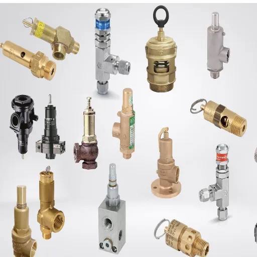 Read More
 -
How the Discharge Valve AC Affects Performance and Longevity of Cooling Systems
December 15, 2025The efficiency of any air conditioning system relies heavily on the precise coordination of its internal components. While the com Read More

Contact Us
Recommended Products
-
 DN1000 Insertion Type Ultrasonic Flow Meter for Clean Water Pure WaterNegotiableMOQ: 100 Sets
 -
Advanced Electromagnetic Flowmeter With Integrated Liquid Measurement TechnologyNegotiableMOQ: 10 Units
-
High Precision Electromagnetic Flow Meter for Southeast Asia Export - Easy Installation & Reliable After-SaleNegotiableMOQ: 10 Units
-
Advanced Digital Vortex Flow Meter for Accurate Water and Liquid MeasurementNegotiableMOQ: 10 Pieces
-
DN50 304 Stainless Steel Turbine Flowmeter for Diesel Oil MeasurementNegotiableMOQ: 10 Units
-
Low-Temperature Turbine Flowmeter for Liquid Nitrogen Applications in Cryogenic SystemsNegotiableMOQ: 10 Units
-
Industrial UV Disinfection Machine for Food & Beverage Industry - UVTunnelTM Tech, 1-40℃ Working TempNegotiableMOQ: 1 Set
-
C 7635 High-purity Water Conductivity Transmitter With Automatic Temperature Compensation 0-100°CNegotiableMOQ: 1 Set
-
C 3655 Conductivity Meter Output Conductivity Transmitter With IP65 Waterproof HousingNegotiableMOQ: 1 Set
-
High Performance Electric Regulating Valve for Environmental Protection Water Treatment SystemsNegotiableMOQ: 1 Piece

-
High Quality Pneumatic Control Valve for Chemical Pharmaceutical Industry Chinese Strong Factory With Spot StockNegotiableMOQ: 1 Piece
-
Pneumatic or Electric Actuator Compatible Full Fluorine-Lined Butterfly Valve With On/Off and Smart Regulating OptionsNegotiableMOQ: 1 Set
-
Powder Conveying Specialized Pneumatic Y-Type Ball Valve, Full Bore Design With No Dead Space for Clean MediaNegotiableMOQ: 1 Set
-
Manual, Pneumatic, or Electric Flanged Ball Valve With ISO5211 High Platform, Easy 90-Degree Operation for Fluid ControlNegotiableMOQ: 1 Set
-
Zero Leakage Full Fluorine-Lined Butterfly Valve Featuring Superior Corrosion Resistance and Long Service LifeNegotiableMOQ: 1 Set
-
Bottom Discharge Valve VTF-88-3 Series, DN25-DN300, Stainless Steel 316L/Carbon Steel, PN10/PN16 Class 150, Manual or Pneumatic ActuationNegotiableMOQ: 1 Set
-
Cost-Effective Knife Gate Valve With Rigid/Elastic Gate Options - Ensures Tight Shutoff and High Performance in Diverse Industrial SettingsNegotiableMOQ: 1 Set
-
FLS PH/ORP 200 Epoxy Resin Body Glass Bulb Electrode (Single-Junction/Double-Junction Versions)NegotiableMOQ: 100 Pieces
-
FLS F3.20 Flow Sensor Optimized for HVAC Systems, Cooling Units, and Boiler Feed Water, Featuring Low Maintenance and High Precision AccuracyNegotiableMOQ: 100 Pieces
-
FLS F3.80 Oval Gear Flow Sensor – High Precision for High-Viscosity Liquids (10-150L/h, IP65)NegotiableMOQ: 100 Pieces