
The Science Behind the Control Valve Working Principle and Its Industrial Applications
In any industrial process, from refining oil to manufacturing pharmaceuticals, precision is paramount. A slight deviation in flow, pressure, or temperature can compromise an entire operation. This is where control valves come in. These critical devices are the final control elements in most industrial systems, acting as the hands that adjust and regulate process variables. Understanding the control valve working principle is essential for any engineer or technician aiming to optimize system performance, enhance safety, and improve efficiency.
This comprehensive guide will explain the science behind how control valves operate. We will cover their fundamental components, the different types available, and their integration with actuators and positioners. You'll also learn how these valves function within automated industrial systems and explore the future trends shaping this technology. By the end, you will have a solid foundation for selecting, operating, and maintaining control valves in various industrial applications.
Understanding Control Valves and Their Working Principles
What Is a Control Valve?
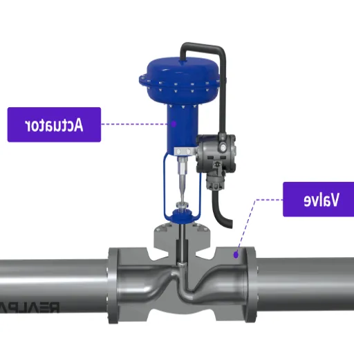
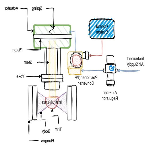
A control valve is a power-operated device that modifies the fluid flow rate in a process control system. It consists of a valve body, an internal trim, and an actuator. The valve works by positioning a movable part (like a plug, disc, or ball) relative to a stationary seat within the valve body. This action changes the size of the flow passage, thereby controlling the amount of fluid that can pass through.
Unlike a simple on/off valve, a control valve can operate at any position between fully open and fully closed. This capability for intermediate positioning is what allows for the precise regulation of process conditions. A control signal from a system controller (like a PLC or DCS) directs the valve’s actuator to move the closure element to the required position, ensuring the process variable stays at its desired setpoint.
Basic Working Principle of Control Valves
The fundamental working principle of a control valve is based on restricting flow. By creating a variable restriction in a fluid pipeline, the valve manipulates the flow rate. The process works as follows:
Sensing: A sensor in the system measures the current state of a process variable, such as pressure or temperature.
Comparing: A controller compares this measurement to the desired setpoint. If there is a difference, the controller calculates the necessary correction.
Actuating: The controller sends a signal (typically pneumatic, electric, or hydraulic) to the valve's actuator.
Modulating: The actuator converts this signal into mechanical motion, moving the valve's closure element (plug, ball, etc.) to adjust the opening. This change in the flow area increases or decreases the fluid flow, bringing the process variable back to the setpoint.
For example, if the temperature in a chemical reactor rises above its setpoint, the controller will signal the control valve to reduce the flow of hot steam into the reactor's heating jacket. This precise modulation is what makes control valves indispensable in automated industrial processes.
Components of Control Valves
A control valve is an assembly of several critical parts. The main components include:
Valve Body: The main pressure-containing structure of the valve, which houses the internal trim and connects to the piping system.
Bonnet: The cover for the opening in the valve body. It supports the actuator and contains the packing that seals against fluid leakage along the stem.
Trim: The internal parts of the valve that come into contact with the fluid. The trim determines the valve's flow characteristics and includes the closure element (plug, ball, or disc), seat, stem, and cage.
Actuator: The "engine" of the valve. It is the device that physically moves the trim to control the flow. Actuators can be pneumatic, electric, or hydraulic.
Positioner: An accessory that ensures the valve stem reaches the precise position dictated by the control signal. It compares the stem's actual position to the controller's command and adjusts the actuator accordingly to eliminate any error.
Types of Control Valves and Their Applications
Overview of Different Valve Types
Choosing the right valve depends on factors like the required flow characteristic, pressure drop, fluid properties (e.g., viscosity, corrosiveness), and shutoff requirements.
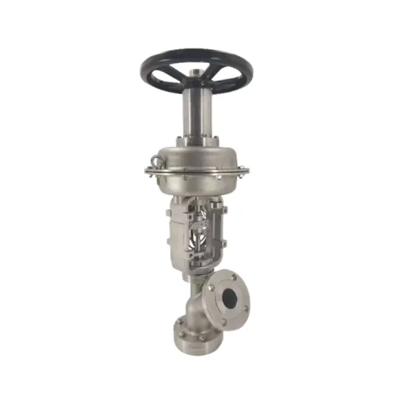
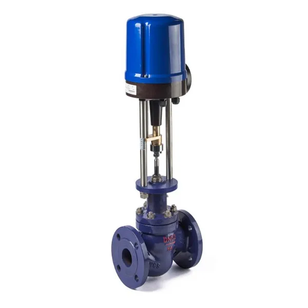
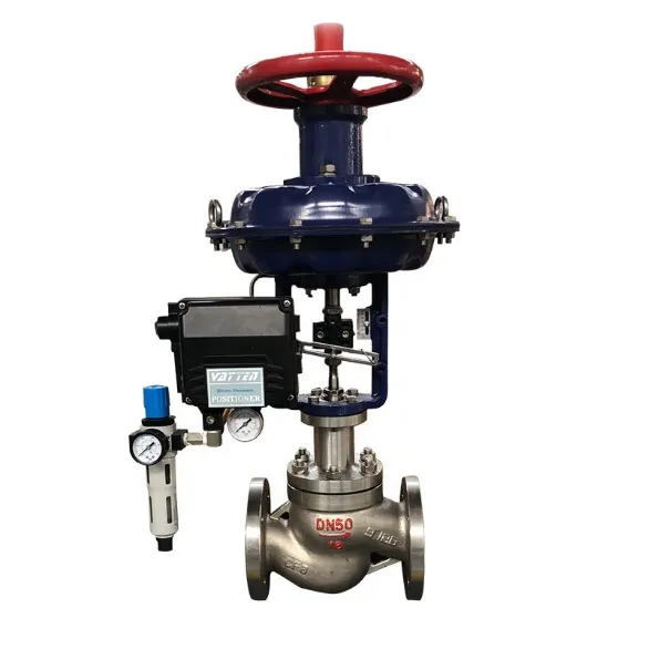
Globe Valves: These are linear-motion valves known for their excellent throttling capability and precise flow control. They are commonly used in applications where tight regulation is more important than minimizing pressure drop.
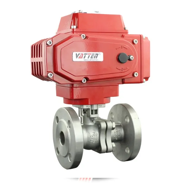
Ball Valves: Rotary-motion valves that use a rotating ball with a bore through it. They offer excellent shutoff capabilities, low pressure drop, and are suitable for clean and slurry services.
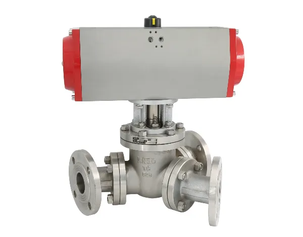
Plug Valves: Similar to ball valves, these rotary valves use a cylindrical or tapered plug to control flow. They are often used for on/off and throttling services with slurries.
Diaphragm Valves: Linear-motion valves that use a flexible diaphragm to start, stop, or throttle flow. They are ideal for corrosive fluids and slurries, as the fluid is isolated from the valve’s operating parts.
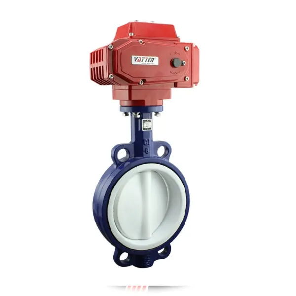
Butterfly Valve: Features and Applications
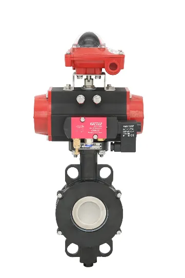
The butterfly valve is a rotary-motion valve that uses a rotating disc to control fluid flow.
Features: Butterfly valves are lightweight, compact, and relatively inexpensive compared to other valve types of the same size. They offer a low pressure drop when fully open and can be actuated quickly. High-performance butterfly valves provide good throttling and tight shutoff.
Applications: Their simple design makes them suitable for a wide range of applications, especially in large-diameter pipelines. They are commonly used in water treatment, chemical services, and HVAC systems. However, standard butterfly valves may not be ideal for highly precise throttling or for handling abrasive slurries, as the disc is always exposed to the flow.
Gate Valve: When to Use It
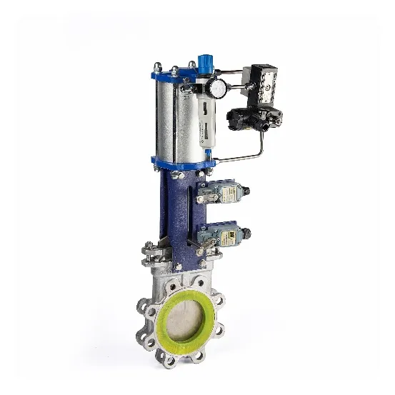
The gate valve is a linear-motion valve that uses a flat closure element, or "gate," that slides into the flow stream to stop the fluid.
Features: Gate valves are designed primarily for on/off service. When fully open, they offer minimal flow restriction and very low pressure drop. They provide tight sealing and are not intended for throttling, as partial opening can cause vibration and damage to the gate and seat.
Applications: Gate valves are excellent for applications requiring full, unobstructed flow, such as isolation valves in pipelines. They are widely used in oil and gas, power plants, and water treatment facilities where the valve will remain either fully open or fully closed for long periods.
Actuators and Positioners in Control Valve Systems
Role of Actuators in Control Valves
The actuator is the component responsible for moving the valve's closure element. It receives a control signal and converts it into the motion needed to open, close, or modulate the valve.
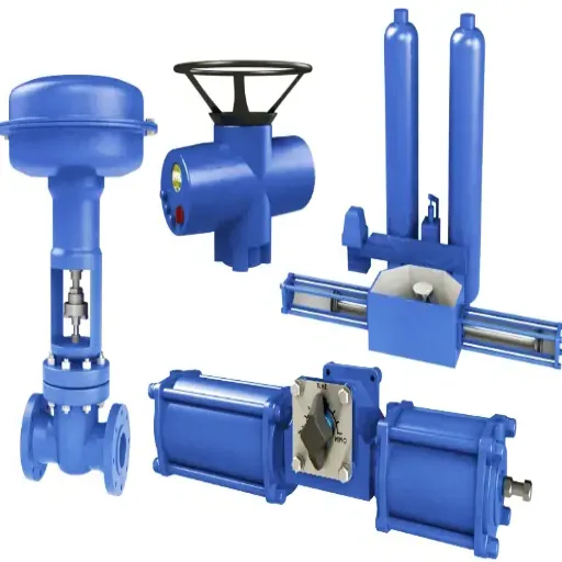
The most common types of actuators are:
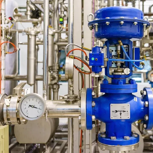
Pneumatic Actuators: These use compressed air to generate motion. They are widely popular due to their simplicity, reliability, and low cost. Diaphragm and piston actuators are two common pneumatic designs.
Electric Actuators: These use an electric motor to drive the valve stem. They offer precise positioning and are ideal for remote locations where compressed air is not available. They can, however, be slower and more expensive than pneumatic options.
Hydraulic Actuators: Using a pressurized fluid like oil, these actuators can generate immense force, making them suitable for high-pressure applications and large valves.
Understanding Valve Positioners
A positioner is a device that improves the performance of a control valve by ensuring the valve stem is in the exact position required by the controller. It acts as a closed-loop controller for the valve itself.
A positioner works by:
Receiving the control signal from the system controller.
Measuring the actual position of the valve stem via a feedback link.
Comparing the desired position (from the control signal) with the actual position.
If there is a discrepancy, the positioner adjusts the pressure to the actuator until the stem reaches the correct position.
Positioners are crucial for overcoming issues like friction in the valve packing, pressure imbalances on the plug, and actuator limitations. This results in faster response times, reduced deadband, and more accurate flow control.
Integration of Actuators and Positioners
The seamless integration of the actuator and positioner is key to a high-performing control valve. Modern "smart" positioners combine digital technology with advanced diagnostics. These devices can not only position the valve with extreme accuracy but also monitor the valve's health, predict maintenance needs, and communicate performance data back to the central control system. This integration turns a simple mechanical device into an intelligent part of the process automation ecosystem.
Principles of Control Valves in Industrial Automation
Control Actions and Their Importance
Control valves are classified by their "fail-safe" action—the position they move to upon loss of power or control signal. This is a critical safety feature.
Fail-Open (FO): The valve opens when the signal is lost. This is used in applications where continued flow is necessary for safety, such as providing cooling water to a reactor.
Fail-Closed (FC): The valve closes when the signal is lost. This is common in applications where stopping the flow is the safest action, such as shutting off the fuel supply to a burner.
Fail-in-Place: The valve remains in its last position upon signal loss.
The choice of control action is determined through a careful risk analysis of the process to ensure the system defaults to its safest possible state during a failure.
Automation and Control Valve Efficiency
In an automated system, the efficiency of a control valve is measured by its ability to respond quickly and accurately to the controller's commands. A well-selected and properly sized valve minimizes process variability, which leads to:
Improved Product Quality: Consistent process conditions result in a more uniform product.
Reduced Energy Consumption: By avoiding overshoot and maintaining steady operation, valves help optimize the use of energy for heating, cooling, and pumping.
Enhanced Safety: Stable processes are safer processes. Reliable valve operation prevents dangerous fluctuations in pressure or temperature.
Increased Throughput: By running the process closer to its optimal setpoints, overall production can be maximized.
The performance of the entire control loop—sensor, controller, and valve—is only as good as its weakest link. A sluggish or inaccurate control valve can undermine the most sophisticated control algorithm.
Future Trends in Control Valve Technology
The technology behind control valves continues to evolve, driven by the demands of Industry 4.0 and the need for smarter, more efficient industrial processes.
Key future trends include:
Smart Valves and Digitalization: The integration of microprocessors and advanced sensors is making valves more intelligent. Smart valves can perform self-diagnostics, communicate wirelessly, and provide a wealth of data on process conditions and valve health. This supports predictive maintenance strategies and reduces downtime.
Additive Manufacturing (3D Printing): 3D printing is enabling the creation of complex valve geometries optimized for specific flow conditions. This can lead to improved performance, reduced cavitation, and lower noise levels. It also allows for rapid prototyping and the production of custom or obsolete parts on demand.
Advanced Materials: The development of new alloys, ceramics, and polymers is expanding the application range of control valves. These materials offer enhanced resistance to corrosion, erosion, and extreme temperatures, allowing valves to operate reliably in increasingly harsh environments.
Energy Efficiency: There is a growing focus on designing valves that minimize energy loss. This includes optimizing flow paths to reduce pressure drop and developing more efficient actuators that consume less power.
Recently Posted
-
Understanding the Functions of Suction Valve and Discharge Valve in Pump Systems
December 18, 2025Industrial pump systems rely on precise mechanical coordination to transport fluids effectively. At the heart of this process are Read More
 -
Exploring Advanced Technologies in Air Compressor Discharge Valve Manufacturing
December 17, 2025The efficiency of any pneumatic system relies heavily on the performance of its smallest components. Among these, the air compress Read More
 -
Exploring Different Discharge Valve Types for Efficient Fluid Flow Management
December 16, 2025Industrial systems rely heavily on precision components to maintain safety, efficiency, and operational integrity. Among these com Read More
 -
How the Discharge Valve AC Affects Performance and Longevity of Cooling Systems
December 15, 2025The efficiency of any air conditioning system relies heavily on the precise coordination of its internal components. While the com Read More

Contact Us
Recommended Products
-
 DN1000 Insertion Type Ultrasonic Flow Meter for Clean Water Pure WaterNegotiableMOQ: 100 Sets
 -
Advanced Electromagnetic Flowmeter With Integrated Liquid Measurement TechnologyNegotiableMOQ: 10 Units
-
High Precision Electromagnetic Flow Meter for Southeast Asia Export - Easy Installation & Reliable After-SaleNegotiableMOQ: 10 Units
-
Advanced Digital Vortex Flow Meter for Accurate Water and Liquid MeasurementNegotiableMOQ: 10 Pieces
-
DN50 304 Stainless Steel Turbine Flowmeter for Diesel Oil MeasurementNegotiableMOQ: 10 Units
-
Low-Temperature Turbine Flowmeter for Liquid Nitrogen Applications in Cryogenic SystemsNegotiableMOQ: 10 Units
-
Industrial UV Disinfection Machine for Food & Beverage Industry - UVTunnelTM Tech, 1-40℃ Working TempNegotiableMOQ: 1 Set
-
C 7635 High-purity Water Conductivity Transmitter With Automatic Temperature Compensation 0-100°CNegotiableMOQ: 1 Set
-
C 3655 Conductivity Meter Output Conductivity Transmitter With IP65 Waterproof HousingNegotiableMOQ: 1 Set
-
High Performance Electric Regulating Valve for Environmental Protection Water Treatment SystemsNegotiableMOQ: 1 Piece

-
High Quality Pneumatic Control Valve for Chemical Pharmaceutical Industry Chinese Strong Factory With Spot StockNegotiableMOQ: 1 Piece
-
Pneumatic or Electric Actuator Compatible Full Fluorine-Lined Butterfly Valve With On/Off and Smart Regulating OptionsNegotiableMOQ: 1 Set
-
Powder Conveying Specialized Pneumatic Y-Type Ball Valve, Full Bore Design With No Dead Space for Clean MediaNegotiableMOQ: 1 Set
-
Manual, Pneumatic, or Electric Flanged Ball Valve With ISO5211 High Platform, Easy 90-Degree Operation for Fluid ControlNegotiableMOQ: 1 Set
-
Zero Leakage Full Fluorine-Lined Butterfly Valve Featuring Superior Corrosion Resistance and Long Service LifeNegotiableMOQ: 1 Set
-
Bottom Discharge Valve VTF-88-3 Series, DN25-DN300, Stainless Steel 316L/Carbon Steel, PN10/PN16 Class 150, Manual or Pneumatic ActuationNegotiableMOQ: 1 Set
-
Cost-Effective Knife Gate Valve With Rigid/Elastic Gate Options - Ensures Tight Shutoff and High Performance in Diverse Industrial SettingsNegotiableMOQ: 1 Set
-
FLS PH/ORP 200 Epoxy Resin Body Glass Bulb Electrode (Single-Junction/Double-Junction Versions)NegotiableMOQ: 100 Pieces
-
FLS F3.20 Flow Sensor Optimized for HVAC Systems, Cooling Units, and Boiler Feed Water, Featuring Low Maintenance and High Precision AccuracyNegotiableMOQ: 100 Pieces
-
FLS F3.80 Oval Gear Flow Sensor – High Precision for High-Viscosity Liquids (10-150L/h, IP65)NegotiableMOQ: 100 Pieces