
Step-by-Step Guide on How Do You Install a Flow Sensor for Accurate Measurements
Installing a flow sensor with precision is necessary for getting accurate and reliable measurements in fluid monitoring systems. Whether you want to optimize industrial processes, improve system efficiency, or acquire data for any critical analysis, correct installation affects optimum operational efficiency. It therefore reduces the chances of error or false malfunctioning. This guide helps walk you through the fundamental steps in flow sensor installation through a very detailed and hands-on approach to eliminate any guesswork. By the time you finish reading this article, you will feel pleasant and confident to install any flow sensor by yourself and have it work according to your operational needs. Now, continue reading to get some tricks and best practices for success.
Understanding Flow Sensors
What Is a Flow Sensor?
It measures flow rate and quantity of fluids-operating in the engineering sense, and thus may include liquid or gas. These are measured on the parameters-confounding factors-as, for instance, velocity or displacement of the column and are translated into electrical signals for on-site monitoring and analyzing by means of different types of transducers and equipments. The latest in the modern flow sensors employs advanced electromagnetic, ultrasonic, and thermal principles, imparting highest precision in reading to configure them for different industrial applications. From water treatment plants on the one hand for resource management to chemical and pharmaceutical plants on the other for automation and process control, these are vital in streamlining processes and bringing in maintenance control.
Types of Flow Sensors
Electromagnetic Flow Sensors: Electromagnetic flow sensors operate based on Faraday's Law of Electromagnetic Induction. This law applies to fluids: While the fluid passes through a magnetic field, it generates voltage proportional to the velocity of conduction in the given media. Therefore, these sensors are widely used for water, wastewater, and slurry applications. Their main advantages are that an electromagnetic flow sensor is highly accurate and is not sensitive to pressure drops. Moreover, these sensors are well-suited for large pipe diameters and practically require very little maintenance.
Ultrasonic Flow Sensors: To calculate fluid velocity, ultrasonic flow sensors make use of sound waves. Basically, this type is divided into two-the transit-time and the Doppler flow-meter. As far as transit time is concerned, it calculates the flow rate by noting the time difference of ultrasonic pulses which are sent upstream and downstream, whereas Doppler flowmeters sense the frequency change produced by particles and bubbles in the flow. These sensors work on a non-intrusive principle and, thus, are applied for clean liquids and gases; most applications are in energy and HVAC industries.
Thermal flow sensors: They work by measuring the heat transfer caused by fluid flow past a heated element. There are two main methods to achieve this: the constant power and constant temperature differential methods, both of which provide extremely accurate measurements primarily suited for low flow. These are typically used for gas consumption and leak detection and are compatible within industrial processes requiring accurate gas flow measurements.
Vortex Flow Sensors: These sensors utilize the Von Kármán Vortex Street principle, in which alternating vortices are released downstream of the bluff body by the flow in an oscillatory fashion. Observation of the frequency of these vortices helps in calculating the flow rate. These sensors are very robust and fit for use in power generation, steam systems, and chemical processing industries where the working fluid could be steam, gas, or liquids.
Coriolis Flow Sensors: With disturbances in oscillation induced by fluid movement in tubes, Coriolis flow sensors measure the mass flow directly based on that. They specialize in accurate measurements for the two states of matter: liquids and gases-whether affected by temperature, pressure, or viscosity variations. This type of sensor is great for applications requiring extremely precise amounts to be dosed or blended together, such as in food and beverage or pharmaceuticals.
Turbine Flow Sensors: With this flow sensor type, a rotor is placed in the fluid stream, and the rotor's speed of rotation is directly proportional to flow. These sensors are highly accurate with clean and low-viscosity fluids and are usually cheaper than others. Thus, once cost-effectiveness ranks to the highest degree, they are mostly used in fuel and water distribution systems.
Flow sensors are used in many testing and operational applications. Thus, there has to be a solution for every industry-based problem. Understanding their operating principles and characteristics helps industries choose the correct type of sensor for increased efficiency and reliability of the process.
Applications of Flow Sensors
Due to their ability to provide accurate measurements and monitoring fluid dynamics in real-time situations, flow sensors find their applications in multiple industries. In industrial processes, flow sensors are used to ensure efficacious operation of the system in such systems as chemical production, oil and gas pipelines, and water treatment plants. In chemical processing, for instance, they control the flow of raw materials to ensure consistent product quality and to prevent system failures.
Flow sensors monitor the flow of air and the distribution of fluids in the HVAC (Heating, Ventilating, and Air Conditioning) sector to maximize energy efficiency and provide an agreeable environment. On the other hand, medical engineering permits their use in ventilators, anesthetic machines, and dialysis machines, where accurate flow measurements assure patient safety.
In fact, flow sensors are vital to renewable energy initiatives that check on turbine efficiencies for hydro plants or measure hydrogen flow in fuel cell systems. With the evolution of the Internet of Things, the forensics of flow sensor activity in a geographical area or flow data made available in real time have led not only to predictive maintenance everywhere but also to increased reliability of operations and decreased downtime for all the implemented systems.
Preparation for Installation
Tools and Materials Needed
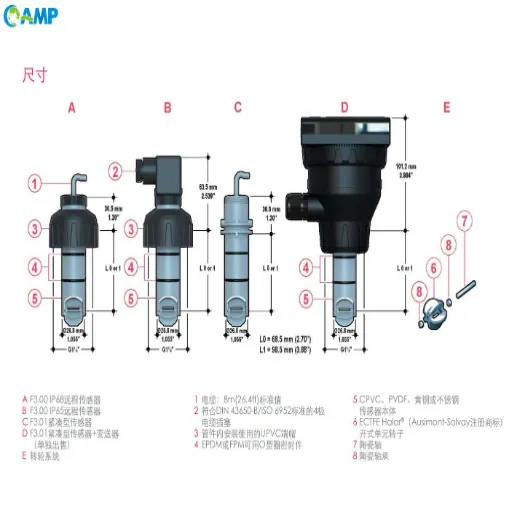
Flow Sensor Unit – Ensure that the sensor selected is fit for the purposes of the application, considering aspects such as flow range, pressure ratings, and dynamics of the operation.
Mounting Hardware – Appropriate mounting brackets, clamps, or fittings to secure the sensor in place and align it with the pipeline or equipment.
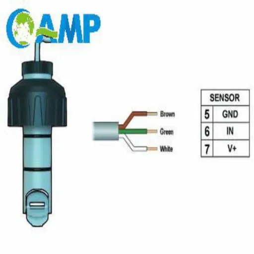
Electrical Wiring Kit – It must contain insulated wires and connectors and include cable management tools to facilitate secure electrical connections to the control system or monitoring device.
Power Supply – A steady and dependable power source should be used, consistent with the specified voltage and current ratings of the sensor.
Calibration Equipment – These are the flow calibrators or reference meters used to check, fine-tune, and adjust the sensor for accuracy during the initial setup.
Sealants and Gaskets – Sealants or gaskets of utmost quality to ensure leak-proof connections in either liquid or gaseous systems. Check compatibility of the material against the medium to be measured.
Screwdrivers and wrenches – The standard set of tools that will assemble mechanics and tighten connections without damaging components.
Diagnostic tool or software interface – In case the system supports digital configuration or troubleshooting, ensure to acquire the necessary diagnostic tools with software interface compatibility for integration and testing.
Protective gears – Should be considered for safety, e.g., gloves and eye protection, and so forth, against hazardous or pressurized media.
The documentation should include user manuals for the system, technical specifications, and wiring diagrams provided by the manufacturer for proper installation and calibration procedures.
If these tools and materials are prepared well in advance, the installation will go smoothly, and one risks fewer delays or errors. Properly and precisely preparing anyone for installation will bring about the very best system functionality.
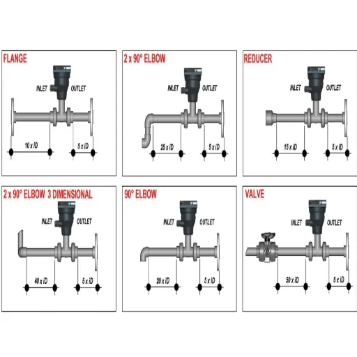
Choosing the Right Location for Installation
The selection of a proper installation site is imperative for the reliability and efficiency of the system. Many considerations must be taken into account during installation. First, ensure that the location provides sufficient accessibility for installation, servicing, and inspection. Restricted access may spur operational inefficiencies and delays in troubleshooting.
Second, environmental considerations such as temperature, humidity, corrosive, or otherwise hazardous atmosphere need to be taken into account because they directly impact the equipment's longevity and proper functioning. Avoid placing equipment at sites exposed to extremes of temperature or moisture unless rated for that environment. EMI should also be checked, mainly for systems susceptible to electrical noise, to maintain signal integrity and stable operation.
It is essential to remember that the location should comply with all relevant standards or codes in the industry, safety requirements included. Adequate spacing, proper ventilation, and structural support must be ensured for protecting system performance and human safety. Considering these factors will make the installation process more efficient and reliable.
Inlet and Outlet Requirements
Proper study and design of inlet and outlet requirements are essential for making sure that the system performs well and lasts for a long time. The inlet should be located such that it allows free and efficient flow of the working fluid without any appreciable turbulence or pressure drop. Consideration should be given to inlet sizes, pressures or operating pressure to which it is subjected, and the type of fluid or material it is handling to prevent corrosion or blocking.
Similarly, outlet design affects the system's overall efficiency. An outlet is to be designed to consider the discharge rate and not permit any backflow or buildup of pressure severally. Assessment must be done on design variables such as the outlet orientation, venting medium, and material choice in the case of high temperatures or high pressures.
With further advancements made in flow dynamics and materials engineering to provide better solutions for customization of inlets or outlets to meet specific operations, such improvements, along with comprehensive system analysis, will ensure that performance criteria are met, safety is assured, and operational efficiency is guaranteed.
Step-by-Step Installation Process
An Operator's Shutdown of the System
To guarantee a secure and efficient system shutdown, a detailed procedure should be followed:
Examine Operational Status:Confirmed the set operational parameters include current values of pressure, temperature, and flow, and that they are within acceptable limits because it would affect any compromise to the system during its closing procedure.
Isolation of Energy Source:Ensure disconnection from energy inlets such as electric and fuel supply. In compressed air or hydraulic power, all may have to be depressurized, making sure to follow safety procedures and instructions in the user's manual.
Valve Closing Procedure:Close all entry and discharge valves gradually and slowly to avoid pressure shock on critical instrument components. Apply manual or automatic means where operational manuals state.
Purge Residual Content:Using the built-in venting mechanism, purge any residual gases, liquids, or other substances from the system. Properly dispose or contain these materials in accordance with environmental and safety laws.
Check for Anomalies:During the shutdown procedure, monitor continuously for unusual behavior, be it sudden changes in pressure, leaks, or vibrations on the equipment. Should these arise, the shut-down process shall immediately halt, and diagnostic tests shall be performed.
Document the Shutdown:Record all relevant information, including timestamps, parameter readings, and observable conditions during the shutdown. Detailed documentation will serve the purpose of traceability and assist in troubleshooting during maintenance or restart activities.
Following these procedures properly will give persons and equipment a controlled and safe shutdown while being compliant with these specifications of operation.
Cutting of Pipe During Installation
When cutting pipe for installation purposes, the measurements and specifications must be corresponding to assure the pipe's proper functioning. Begin by verifying the pipe's dimensions and whether it conforms to installation requirements concerning diameter, length, and material compatibility. Employ proper cutting tools, such as a pipe cutter or mechanical saw, that correspond to the pipe's material to avoid deformation or damage.
Position the pipe in a secure manner, using clamps or a vise, to remove any possible movement during the time of cutting-improper movement can lead to an inaccurate cut. Using a measuring tape and a permanent marker, make a clear mark where the cut will be made. Make sure to double-check the alignment with the installation layout. While cutting, make sure to apply pressure evenly and keep a consistent rhythm; by doing so, you will end up with a nice clean edge that will consequently lessen the need for post-cutting preparation.
Thereafter, examine pipe end for burrs, jagged edges, or irregularities. Such imperfections must be removed with a suitable deburring tool or file, creating a smooth surface that will enable the seal to be tightly fixed in the eventual connection. It is highly advisable to regularly check the calibration of equipment and the sharpness of the blade to maintain precision at all times during the course of the process. Following these steps will give the best possible finish to the pipe and ensure an easy fit into the installation system.
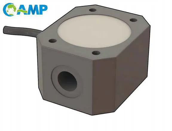
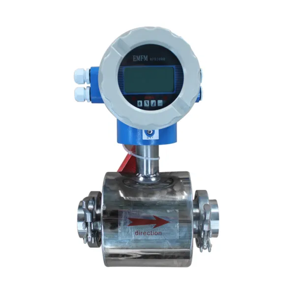
Installing the Flow Sensor
Install the flow sensor by first confirming that the designated portion of the piping system is clean and free from contaminants. Ensure proper alignment by pre-marking the installation points according to the manufacturer's instructions. Using a calibrated torque wrench, install the sensor assembly hardware, taking care not to over-tighten, as this may damage the sensor housing or affect its accuracy. Once the sensor is mounted, connect it with the electrical interface of the system using shielded cables to minimize electromagnetic interference and retain signal integrity. Perform sensor diagnostics to verify that the sensor is communicating with the monitoring system, noting output signals to ensure calibration. Anything less than proper installation would lower system efficiency and reliability of flow measurement.
Post-Installation Setup
Testing the Installation
Once the sensor is installed, confirm that it functions properly by subjecting it to a systematic battery of tests to ascertain its accuracy and reliability. To start with, submit a controlled flow rate through the installation and slowly watch the sensor output signal. Comparison of actual readings of flow with the known flow rate given by the reference meter will determine if the sensor is working correctly or indeed providing the right measurement. Should discrepancies arise, undertake the calibration procedure as given in the manufacturer's manual.
Also, the sensor response time should be evaluated under different flow rates to confirm that it fulfills certain operation requirements. If diagnostic software or monitoring tools are available, utilize them to verify the signal stability and that no noise or other fluctuation that may hinder performance exists. Complete the testing phase by recording all readings and ensuring that in all real-life conditions, the sensor works in-designed limits. Full testing would promote best long-term reliability for the system and accuracy in measurements.
Calibration Procedures for Best Performance
A flow sensor must be calibrated accurately to give precise and reliable measurement results during actual working conditions. Start by connecting the sensor with a certified calibration system which simulates a variety of standard flow rates. Note that it is very important that the calibration medium be the same as the operational fluid since any differences in viscosity or density can highly affect the sensor's response.
The calibration system should be run through a series of initial flow rates that cover the whole operating range of the sensor, noting the output of the sensor at each such flow rate. Compare these outputs with the reference values that the calibration system gives. If any differences are found, then adjust the output of the sensor accordingly, following the adjustment procedure laid down by the manufacturer, normally using onboard software or hardware configuration tools.
For an instrument to be considered sufficiently calibrated, the calibration sequence must be repeated several times, which means there are at least two independent trials. Also, in terms of performance specifications, information regarding the response time of the sensor and its linearity should be developed to ensure these exactly match those specified in the design. After the sequence is completed, all the calibrated settings and data shall be documented and stored for use in maintenance and quality assurance. Correct calibration will help to eliminate any existing inaccuracies and assist with proper sensor interfacing into critical flow management mechanisms.
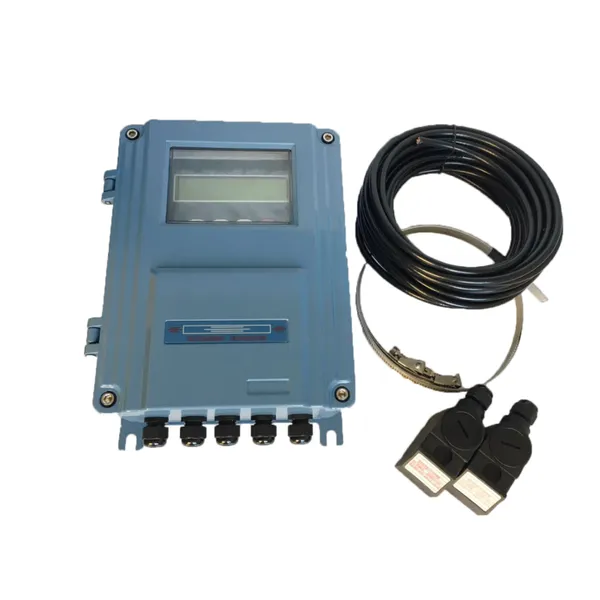
Connecting with Monitoring Systems
In these lines, it wants us to develop a communication protocol that synchronizes with the architecture of monitoring systems. The very first thing to consider is about data transmission: whether they use Modbus, CAN bus, or Ethernet-interfaced protocols. To allow inter-device communication, a standard data format has to be implemented. It should be fail-safe to some extent in case of a lost communication link; for example, if such an event occurs, a requisite amount of critical data must be stored and readily available. In alignment with the monitoring platform, mapping of sensor outputs will keep pace with the system informatics framework, thereby allowing real-time processing of diagnostics and analytics. This all-encompassing connectivity exercise ensures that they perform optimally in an environment that is constituted by complex operational factors.
Troubleshooting Common Issues
Flow Measurement Errors
My approach in addressing flow measurement errors includes identifying the causes of errors and removing them to obtain clean readings, resulting in a system that functions rightly. The flow measurement errors usually occur because of factors such as improper sensor installation, calibration drift, or blockage in the flow path. For instance, if the flow meter is installed downstream of, or in a region where turbulent flow exists upstream, or in no location where it has sufficient straight pipe, measurements can never be right. That is why I ensure that the meter is installed according to manufacturers' instructions-everything else being equal-in low turbulence and good flow profile conditions.
Others also include flow errors due to the entrainment of air bubbles, particulate matter, or non-homogeneous fluid properties, all of which tend to hamper sensor accuracy. I preclude this in liquid flow systems by integrating appropriate filtration systems and degassing units. Maintenance should go periodic, cleaning the flow meters and recalibrating them while tending to drift within their specified tolerance range. Furthermore, I ensure these systems are linked to diagnostic software that constantly scans the flow meters' signals, searching for anomalies such as continuous fluctuations or abrupt changes from the normal range, which could indicate blockage, wear, or other operational issues.
Proper installation, routine maintenance, and the use of advanced troubleshooting methods create a strong approach to reducing errors in flow measurement. Redundant flow sensors and cross-verification techniques increase data reliability while decreasing the system's susceptibility to individual measurement failure. These methods do more than guarantee accuracy; they improve the smooth functioning of industrial and operational workflows.
Sensor Malfunctions
In order to address sensor malfunction, I take a stepwise approach by performing diagnostics of the highest order in addition to following sensor deployment best practices. Flow sensors may malfunction due to several reasons: environmental condition, physical damage, electrical interference, or the sensor drifting over time. I deploy countermeasures against these problems, such as environmental controls with protective housings, temperature controls, and vibration isolation devices. Regular maintenance inspection and calibration processes are also crucial, whereby the sensor's behavior is checked within an accuracy range with the aim of making any drift undetectable.
Punctual detection of an abnormal scenario could rely on data-integration systems showing irregular readings or disparities between input signals. An excellent example is employing modern flow sensors with advanced self-diagnostic features that either observe or detect a malfunction from clogged components or signal degradation affecting further operation unconscious. For instance, multi-variable sensors measuring temperature, pressure, and flow may render yet another layer of verification upon anomaly detection, in conjunction with baseline data. Errors can be localized confidently and swiftly by cross-checking observations with system norms.
The other aspect of failure mitigation is redundancy. Redundancies are designed such that critical systems operate loss-free, or with degradation in some cases, due to sensor placements, assuming that any individual sensor may malfunction. Fault-tolerant architectures in conjunction with such redundancies allow operations to continue uninterrupted as the faulty component is identified and replaced. Combined with vigorous diagnostics, preventive maintenance, and strategic deployment of redundancies, I guarantee sensor failures are resolved quickly and with minimal impact on operational and data accuracy efficiencies.
Flow Sensors Maintenance Tips
Proper maintenance of flow sensors is essential to keep them accurate and reliable over time. Following best practices, I tend to clean and inspect regularly so that problems like clogging or buildup of debris do not crop up, both of which seriously affect performance. I schedule preventative maintenance activities based on the configuration of the systems, such as heavy particulates, widely fluctuating temperature conditions, or corrosive atmospheres, so that wear or contamination can be eliminated before it affects the system accuracy. Cleaning of the instruments is done with non-abrasive instruments and solvents, which do not harm the sensor and preserve its working condition.
The other big thing that needs to be taken into account when flow sensor maintenance is calibration. I follow the manufacturer's recommendations on calibration intervals but, in cases of high stress or critical pressure applications where actual accuracy is absolutely necessary, I shorten the interval. Using certified calibration instruments and standardized procedures ensures that every sensor shall still provide the right amount of measurement. Verification of calibration data shall be logged, reviewed periodically so that if variations from expected performance occur, such variations are corrected immediately.
An important aspect I emphasize is the monitoring of electrical connections and signal outputs. The presence of corrosion or loose wiring can produce intermittent behavior or failures within the system; hence, I regularly check them. Software-based diagnostics are equally vital, for these allow one whereby anomalies, like inconsistent flow rate signals, can be observed in real time and troubleshooting becomes easier. By combining preventive maintenance and improvements in sensor diagnostic and calibration tools, I sustain the flow sensors in a state of operational condition and calibration and minimize at the same time the system downtime.
Recently Posted
-
Understanding the Functions of Suction Valve and Discharge Valve in Pump Systems
December 18, 2025Industrial pump systems rely on precise mechanical coordination to transport fluids effectively. At the heart of this process are Read More
 -
Exploring Advanced Technologies in Air Compressor Discharge Valve Manufacturing
December 17, 2025The efficiency of any pneumatic system relies heavily on the performance of its smallest components. Among these, the air compress Read More
 -
Exploring Different Discharge Valve Types for Efficient Fluid Flow Management
December 16, 2025Industrial systems rely heavily on precision components to maintain safety, efficiency, and operational integrity. Among these com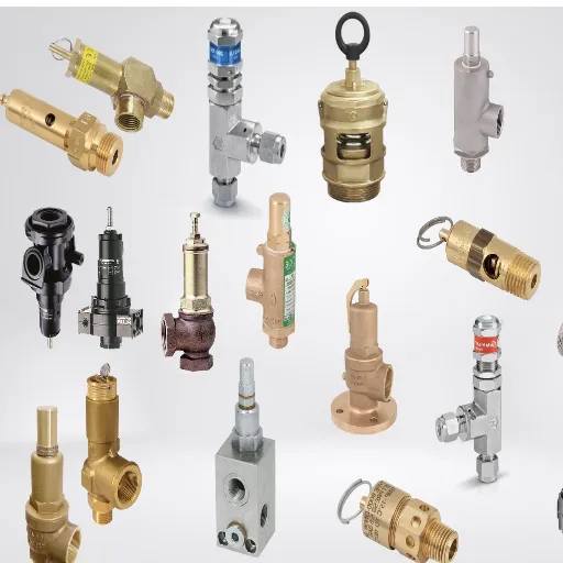 Read More
 -
How the Discharge Valve AC Affects Performance and Longevity of Cooling Systems
December 15, 2025The efficiency of any air conditioning system relies heavily on the precise coordination of its internal components. While the com Read More

Contact Us
Recommended Products
-
 DN1000 Insertion Type Ultrasonic Flow Meter for Clean Water Pure WaterNegotiableMOQ: 100 Sets
 -
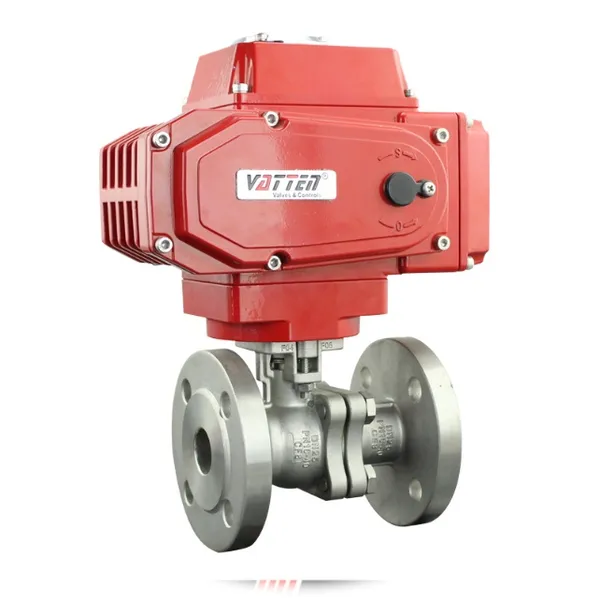
Advanced Electromagnetic Flowmeter With Integrated Liquid Measurement TechnologyNegotiableMOQ: 10 Units
-
High Precision Electromagnetic Flow Meter for Southeast Asia Export - Easy Installation & Reliable After-SaleNegotiableMOQ: 10 Units
-
Advanced Digital Vortex Flow Meter for Accurate Water and Liquid MeasurementNegotiableMOQ: 10 Pieces
-
DN50 304 Stainless Steel Turbine Flowmeter for Diesel Oil MeasurementNegotiableMOQ: 10 Units
-
Low-Temperature Turbine Flowmeter for Liquid Nitrogen Applications in Cryogenic SystemsNegotiableMOQ: 10 Units
-
Industrial UV Disinfection Machine for Food & Beverage Industry - UVTunnelTM Tech, 1-40℃ Working TempNegotiableMOQ: 1 Set
-
C 7635 High-purity Water Conductivity Transmitter With Automatic Temperature Compensation 0-100°CNegotiableMOQ: 1 Set
-
C 3655 Conductivity Meter Output Conductivity Transmitter With IP65 Waterproof HousingNegotiableMOQ: 1 Set
-
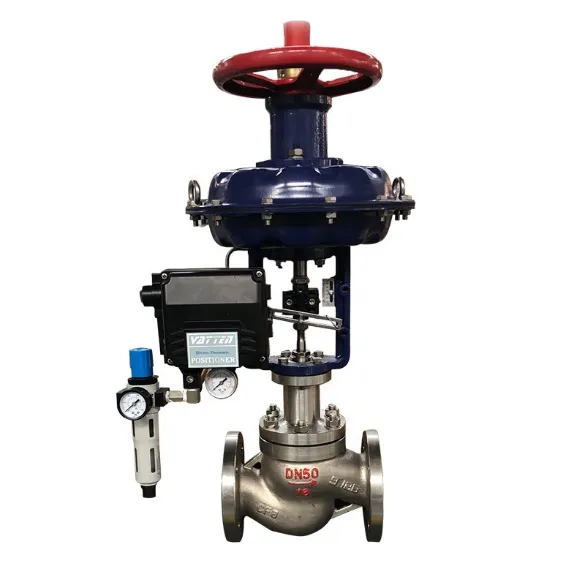
High Performance Electric Regulating Valve for Environmental Protection Water Treatment SystemsNegotiableMOQ: 1 Piece
-
High Quality Pneumatic Control Valve for Chemical Pharmaceutical Industry Chinese Strong Factory With Spot StockNegotiableMOQ: 1 Piece
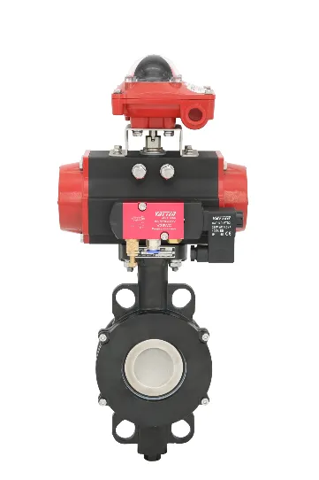
-
Pneumatic or Electric Actuator Compatible Full Fluorine-Lined Butterfly Valve With On/Off and Smart Regulating OptionsNegotiableMOQ: 1 Set
-
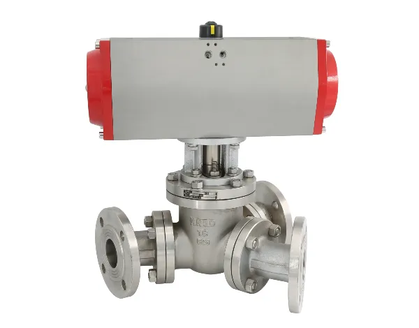
Powder Conveying Specialized Pneumatic Y-Type Ball Valve, Full Bore Design With No Dead Space for Clean MediaNegotiableMOQ: 1 Set
-
Manual, Pneumatic, or Electric Flanged Ball Valve With ISO5211 High Platform, Easy 90-Degree Operation for Fluid ControlNegotiableMOQ: 1 Set
-
Zero Leakage Full Fluorine-Lined Butterfly Valve Featuring Superior Corrosion Resistance and Long Service LifeNegotiableMOQ: 1 Set
-
Bottom Discharge Valve VTF-88-3 Series, DN25-DN300, Stainless Steel 316L/Carbon Steel, PN10/PN16 Class 150, Manual or Pneumatic ActuationNegotiableMOQ: 1 Set
-
Cost-Effective Knife Gate Valve With Rigid/Elastic Gate Options - Ensures Tight Shutoff and High Performance in Diverse Industrial SettingsNegotiableMOQ: 1 Set
-
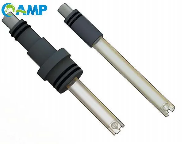
FLS PH/ORP 200 Epoxy Resin Body Glass Bulb Electrode (Single-Junction/Double-Junction Versions)NegotiableMOQ: 100 Pieces
-
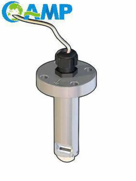
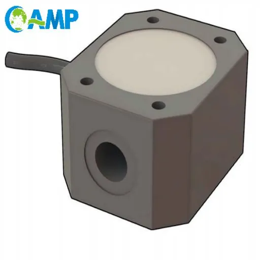
FLS F3.20 Flow Sensor Optimized for HVAC Systems, Cooling Units, and Boiler Feed Water, Featuring Low Maintenance and High Precision AccuracyNegotiableMOQ: 100 Pieces
-
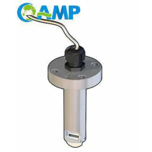
FLS F3.80 Oval Gear Flow Sensor – High Precision for High-Viscosity Liquids (10-150L/h, IP65)NegotiableMOQ: 100 Pieces