
 Business License

Understanding the Discharge Valve Function in Industrial Pumping Systems and Applications
In the complex ecosystem of industrial fluid dynamics, the stability and efficiency of a system often hinge on the performance of relatively small components. Among these, the discharge valve serves as a critical gatekeeper. Whether located in a massive centrifugal pump setup within a water treatment plant or integrated into a high-pressure boiler system, the discharge valve dictates the flow of medium out of the compression or pumping chamber and into the process line.
Understanding the function, mechanics, and maintenance of these valves is not merely a matter of operational knowledge—it is a requirement for ensuring safety, longevity, and energy efficiency in industrial applications. This guide examines the technical intricacies of discharge valves, their specific roles in pumping and boiler systems, and the protocols required to maintain their optimal functionality.
Understanding the Role of Discharge Valves
Definition and Importance of Discharge Valves
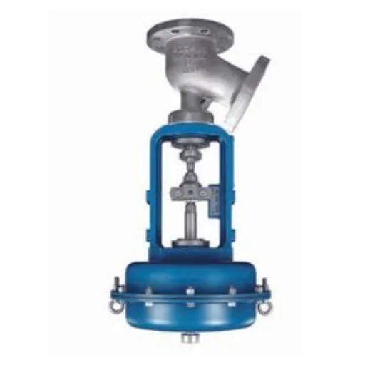
A discharge valve is a mechanical device designed to regulate the flow of fluid or gas leaving a pump, compressor, or pressure vessel. Its primary function is to prevent backflow (reverse flow) into the machinery when the system is idle or during the intake stroke, while simultaneously allowing the medium to exit freely during the discharge cycle.
In many industrial configurations, the term "discharge valve" can refer to two distinct components depending on the context: the internal check mechanism within a reciprocating pump or compressor, or the external isolation/control valve located on the discharge piping of a centrifugal pump. Both serve the overarching goal of maintaining system pressure and directing flow, but their operational mechanics differ.
Overview of Industrial Pumping Systems
In an industrial pumping system, the discharge valve acts as the final control element before the fluid enters the distribution network. When a pump generates pressure, the discharge valve must open efficiently to minimize pressure drop. Conversely, as soon as the pressure generation ceases—either at the end of a piston stroke or when a centrifugal pump is shut down—the valve must seal instantly. Failure to do so results in backflow, which can cause catastrophic damage to pump impellers, introduce hydraulic shock (water hammer) to the piping, and significantly reduce energy efficiency.
Role of Discharge Valves in Boiler Systems
In boiler applications, discharge valves often take the form of blowdown valves. These are specialized components critical for maintaining water chemistry and system integrity. As water evaporates in a boiler, dissolved solids remain behind, increasing the concentration of impurities. If left unchecked, these solids form scale, reducing heat transfer and causing corrosion.
The discharge (or blowdown) valve allows operators to remove a portion of this concentrated water from the boiler. This process, often automated based on conductivity sensors, ensures that the water quality remains within safe operating parameters. The valve must withstand extreme temperatures and pressures, making its material composition and design tolerance vital for safe boiler operation.
Working Principle of Discharge Valves
How Discharge Valves Operate
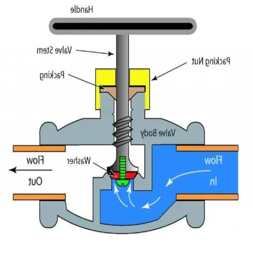
In a standard reciprocating compressor or pump, the discharge valve remains closed during the suction stroke. The internal cylinder pressure drops below the pressure in the discharge manifold, and the pressure differential—aided by a spring or gravity—keeps the valve seated tightly.
As the piston or plunger moves forward during the compression stroke, the internal pressure rises. Once the pressure inside the cylinder exceeds the combined force of the discharge line pressure and the valve's retaining spring (a threshold known as "cracking pressure"), the valve lifts from its seat. This allows the compressed fluid or gas to escape into the discharge line. The moment flow reaches zero or begins to reverse, the spring and the downstream pressure force the valve back onto its seat, sealing the chamber.
Key Components of Discharge Valves
While designs vary, most discharge valves consist of four primary components:
The Seat: This is the stationary part of the valve body against which the moving element seals. It is often hardened or surfaced with materials like Stellite to resist wear and wire drawing.
The Obdurator (Disc/Ball/Plate): This is the moving element that blocks or allows flow. In high-speed compressors, this is often a lightweight metallic or PEEK plate. In slurry pumps, it might be a heavy ball.
The Spring: This component provides the closing force. It ensures the valve closes quickly before significant reverse flow can occur, minimizing slamming and wear.
The Cage or Retainer: This structure guides the moving element, ensuring it remains aligned with the seat and limiting its travel to prevent over-extension.
Fluid Dynamics and Discharge Valve Efficiency
The efficiency of a discharge valve is governed by fluid dynamics. Engineers aim to maximize the flow coefficient ($Cv$) while maintaining a robust seal. When fluid passes through the valve, turbulence creates a pressure drop. A poorly designed valve with a restrictive flow path forces the pump to work harder, consuming more energy to overcome the resistance.
Furthermore, the valve's response time is critical. In high-frequency reciprocating pumps, the valve may cycle hundreds of times per minute. The fluid inertia and the mass of the valve disc must be perfectly balanced. If the valve is too heavy, it opens late (causing pressure spikes) and closes late (allowing backflow). If it is too light, it may flutter, leading to rapid component fatigue.
Types of Discharge Valves
Type 1: Automatic Non-Return Discharge Valves
These are the most common internal valves found in reciprocating compressors and pumps. They are self-actuating and purely reactive to system pressure.
Design Characteristics: These often feature plate, ring, or channel designs. They are designed for rapid cycling and low pressure drop.
Primary Function: To convert oscillating pressure generation into unidirectional flow.
Industrial Application: Found in natural gas compressors, high-pressure plunger pumps for water jetting, and refrigeration compressors.
Type 2: Modulating Control Discharge Valves
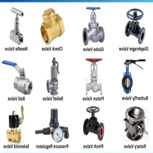
In large centrifugal pump systems, the "discharge valve" is often an external globe, butterfly, or ball valve equipped with an actuator. Unlike the automatic type, these are essentially active components controlled by a central system.
Design Characteristics: These valves are robust and capable of throttling flow. They are linked to a PLC (Programmable Logic Controller) or DCS (Distributed Control System).
Primary Function: To regulate the flow rate, control discharge pressure, and provide system isolation during maintenance. They are frequently used to create backpressure during pump startup to prevent motor overload.
Industrial Application: Water distribution networks, chemical processing plants, and oil refineries where precise flow control is required.
Comparison Between Different Valve Types
Feature | Automatic Non-Return | Modulating Control |
|---|---|---|
Actuation | Differential Pressure (Self-acting) | Electric, Pneumatic, or Hydraulic Actuator |
Response Speed | Milliseconds | Seconds to Minutes |
Primary Goal | Prevent Backflow | Regulate Flow Volume/Pressure |
Complexity | Mechanical simplicity, high precision | Control system integration required |
Maintenance | Seat/Disc replacement | Actuator calibration, seal replacement |
Troubleshooting Discharge Valve Issues
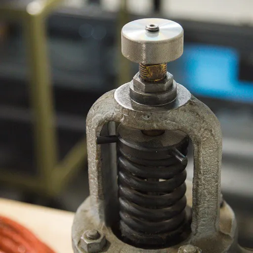
Common Problems with Discharge Valves
1. Leaking and Wire Drawing
The most prevalent issue is leaking across the seat when the valve is closed. In high-pressure steam or gas applications, a small leak allows high-velocity fluid to erode the metal of the seat and disc, creating a channel. This phenomenon, known as wire drawing, rapidly destroys the valve's ability to seal.
2. Valve Flutter
If a discharge valve is oversized for the application, or if the spring tension is incorrect, the valve element may not remain fully open during the discharge stroke. Instead, it oscillates or "flutters" on the seat. This causes rapid wear on the guiding surfaces and the seat itself, leading to premature failure.
3. Carbonization and fouling
In compressor applications, particularly those involving hydrocarbons or lubricated cylinders, heat can cause oil to carbonize on the valve components. This debris prevents the valve from seating fully, leading to leakage. The leakage, in turn, causes re-compression of hot gas, further increasing temperatures and accelerating carbon buildup in a destructive cycle.
Diagnostic Techniques for Valve Malfunctions
Identifying a failing discharge valve requires a systematic approach.
Thermal Analysis: In compressors, a leaking discharge valve causes the discharge temperature to rise significantly above normal operating parameters due to re-compression. Infrared thermometers can quickly identify cylinders running hot.
Acoustic Monitoring: Ultrasonic listening devices can detect the high-frequency "hissing" sound of fluid bypassing a closed valve seat, even in noisy plant environments.
Pressure Waveform Analysis: For reciprocating equipment, analyzing the pressure trace inside the cylinder is the gold standard. A delayed opening or a sloping discharge line on the P-V diagram clearly indicates valve restrictions or leakage.
Preventive Maintenance Tips for Discharge Valves
Reactive maintenance on discharge valves often results in unscheduled downtime. A preventive strategy is far more cost-effective.
Regular Seat Lapping: During scheduled overhauls, valve seats should be inspected and lapped (polished) to restore flatness. This ensures a tight seal and extends the life of the component.
Spring Replacement: Springs fatigue over time and lose their tension. They should be replaced at regular intervals, regardless of their visual appearance, to ensure correct cracking pressure.
Material Upgrades: If a valve fails repeatedly due to corrosion or erosion, consult with the manufacturer about upgrading materials. Switching from standard stainless steel to Inconel or Monel can significantly increase service life in harsh chemical environments.
System Cleanliness: Ensure that suction strainers are intact. Debris entering the pump is the leading cause of discharge valve damage.
Recently Posted
-
Understanding the Functions of Suction Valve and Discharge Valve in Pump Systems
December 18, 2025Industrial pump systems rely on precise mechanical coordination to transport fluids effectively. At the heart of this process are Read More
 -
Exploring Advanced Technologies in Air Compressor Discharge Valve Manufacturing
December 17, 2025The efficiency of any pneumatic system relies heavily on the performance of its smallest components. Among these, the air compress Read More
 -
Exploring Different Discharge Valve Types for Efficient Fluid Flow Management
December 16, 2025Industrial systems rely heavily on precision components to maintain safety, efficiency, and operational integrity. Among these com Read More
 -
How the Discharge Valve AC Affects Performance and Longevity of Cooling Systems
December 15, 2025The efficiency of any air conditioning system relies heavily on the precise coordination of its internal components. While the com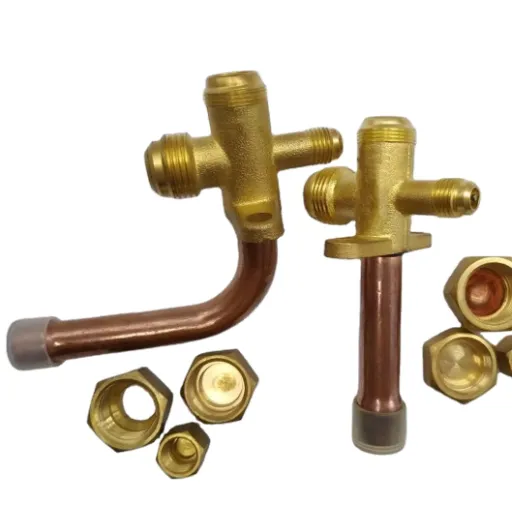 Read More

Contact Us
Recommended Products
-
 DN1000 Insertion Type Ultrasonic Flow Meter for Clean Water Pure WaterNegotiableMOQ: 100 Sets
 -
Advanced Electromagnetic Flowmeter With Integrated Liquid Measurement TechnologyNegotiableMOQ: 10 Units
-
High Precision Electromagnetic Flow Meter for Southeast Asia Export - Easy Installation & Reliable After-SaleNegotiableMOQ: 10 Units
-
Advanced Digital Vortex Flow Meter for Accurate Water and Liquid MeasurementNegotiableMOQ: 10 Pieces
-
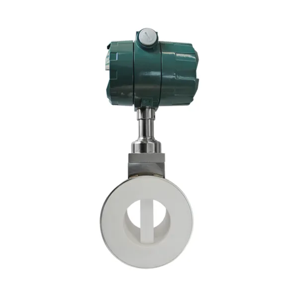
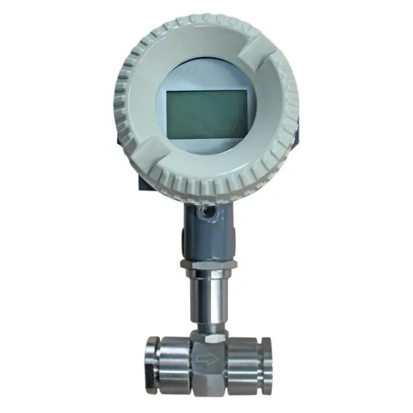
DN50 304 Stainless Steel Turbine Flowmeter for Diesel Oil MeasurementNegotiableMOQ: 10 Units
-
Low-Temperature Turbine Flowmeter for Liquid Nitrogen Applications in Cryogenic SystemsNegotiableMOQ: 10 Units
-
Industrial UV Disinfection Machine for Food & Beverage Industry - UVTunnelTM Tech, 1-40℃ Working TempNegotiableMOQ: 1 Set
-
C 7635 High-purity Water Conductivity Transmitter With Automatic Temperature Compensation 0-100°CNegotiableMOQ: 1 Set
-
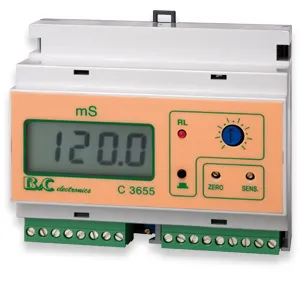
C 3655 Conductivity Meter Output Conductivity Transmitter With IP65 Waterproof HousingNegotiableMOQ: 1 Set
-
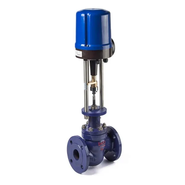
High Performance Electric Regulating Valve for Environmental Protection Water Treatment SystemsNegotiableMOQ: 1 Piece

-
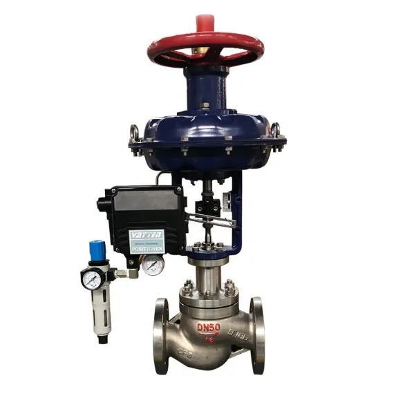
High Quality Pneumatic Control Valve for Chemical Pharmaceutical Industry Chinese Strong Factory With Spot StockNegotiableMOQ: 1 Piece
-
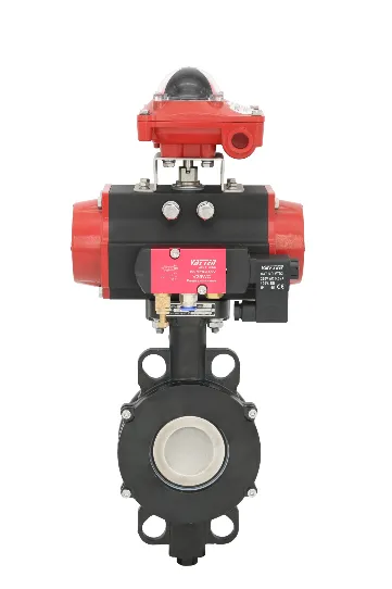
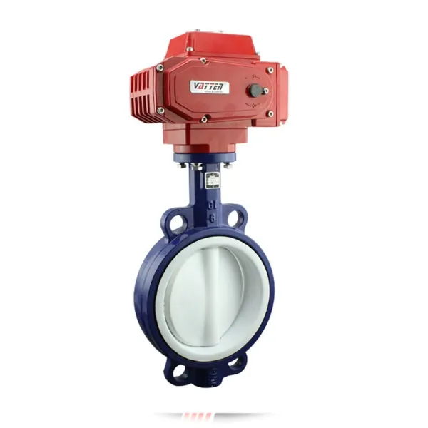
Pneumatic or Electric Actuator Compatible Full Fluorine-Lined Butterfly Valve With On/Off and Smart Regulating OptionsNegotiableMOQ: 1 Set
-
Powder Conveying Specialized Pneumatic Y-Type Ball Valve, Full Bore Design With No Dead Space for Clean MediaNegotiableMOQ: 1 Set
-
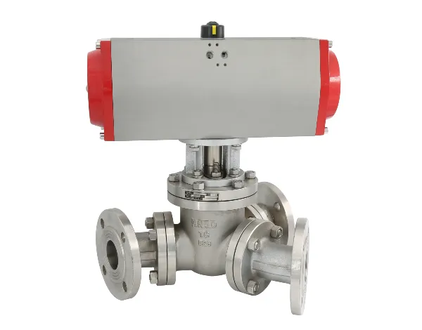
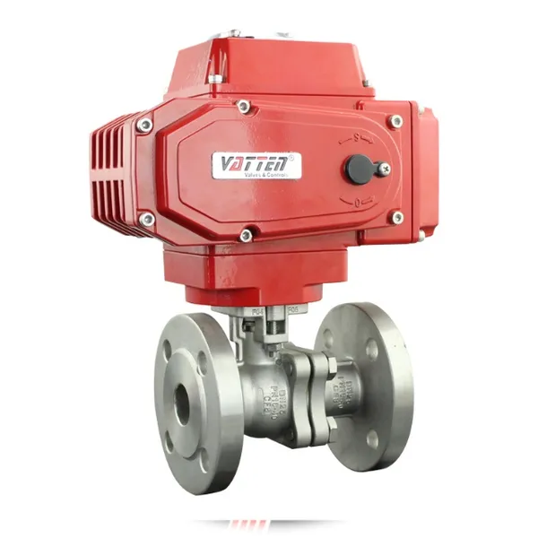
Manual, Pneumatic, or Electric Flanged Ball Valve With ISO5211 High Platform, Easy 90-Degree Operation for Fluid ControlNegotiableMOQ: 1 Set
-
Zero Leakage Full Fluorine-Lined Butterfly Valve Featuring Superior Corrosion Resistance and Long Service LifeNegotiableMOQ: 1 Set
-
Bottom Discharge Valve VTF-88-3 Series, DN25-DN300, Stainless Steel 316L/Carbon Steel, PN10/PN16 Class 150, Manual or Pneumatic ActuationNegotiableMOQ: 1 Set
-
Cost-Effective Knife Gate Valve With Rigid/Elastic Gate Options - Ensures Tight Shutoff and High Performance in Diverse Industrial SettingsNegotiableMOQ: 1 Set
-
FLS PH/ORP 200 Epoxy Resin Body Glass Bulb Electrode (Single-Junction/Double-Junction Versions)NegotiableMOQ: 100 Pieces
-
FLS F3.20 Flow Sensor Optimized for HVAC Systems, Cooling Units, and Boiler Feed Water, Featuring Low Maintenance and High Precision AccuracyNegotiableMOQ: 100 Pieces
-
FLS F3.80 Oval Gear Flow Sensor – High Precision for High-Viscosity Liquids (10-150L/h, IP65)NegotiableMOQ: 100 Pieces