
Understanding How to Work a Conductivity Sensor in Industrial Applications
Conductivity measurement is a fundamental process in numerous industrial and scientific applications, from ensuring the purity of water to managing agricultural nutrients. Understanding how a conductivity sensor works is crucial for anyone involved in these fields. This guide explains the principles behind conductivity sensors, their various types, and best practices for accurate measurement.
Introduction to Conductivity and Its Importance
What is Electrical Conductivity?
Electrical conductivity is a measure of a material's ability to conduct an electric current. In liquids, this current is carried by ions—charged particles that are formed when salts, acids, or bases dissolve in a solvent, typically water. The more ions present in a solution, the higher its conductivity. Pure water, which has very few free ions, is a poor conductor of electricity. However, when substances like salt (sodium chloride) are added, they dissociate into positive (Na+) and negative (Cl-) ions, enabling the water to conduct electricity more effectively.
Applications of Conductivity Measurement
Conductivity is a vital parameter across many sectors because it indicates the total concentration of dissolved ions in a solution. Key applications include:
Water Quality Monitoring: Used in drinking water treatment, wastewater management, and environmental monitoring to assess purity and contamination levels.
Agriculture and Hydroponics: Helps manage the nutrient concentration in irrigation water and hydroponic solutions, ensuring optimal plant growth.
Industrial Processes: Critical in industries such as pharmaceuticals, food and beverage, and power generation, for monitoring processes including demineralization, boiler water control, and cleaning procedures (CIP).
Aquariums and Aquaculture: Essential for maintaining the correct salinity and water conditions for aquatic life.
How Conductivity Sensors Work
Principles of Operation
A conductivity sensor typically consists of two or more electrodes made of conductive materials such essential graphite, stainless steel, or platinum. These electrodes are placed into the solution to be measured.
An alternating voltage (AC) is applied to the electrodes. Using AC is essential to prevent electrolysis and polarization, which would alter the solution's chemistry and lead to inaccurate readings.
The ions in the solution move towards the electrode with the opposite charge, creating an electrical current.
The sensor measures how easily this current flows between the electrodes.
This measurement is then converted into a conductivity value by a connected meter, usually reported in units like Siemens per meter (S/m) or, more commonly, microsiemens per centimeter (µS/cm) or millisiemens per centimeter (mS/cm).
The measured conductance depends on the sensor's geometryconductive materials such as. Therefore, a "cell constant" is used to normalize the reading for the distance between the electrodes and their surface area. The final conductivity reading is calculated as: Conductivity = Measured Conductance x Cell Constant.
Types of Conductivity Probes
There are three primary types of conductivity sensors, each suited for different applications and conductivity ranges.
Amperometric (2-Electrode) Sensors
These are the most common and basic types of sensors.depends on the sensor's geometry They consist of two electrodes and are ideal for measuring low to medium conductivity levels, such as in pure water or tap water. Their simple design makes them cost-effective, but they can be susceptible to inaccuracies from polarization and contamination in high-conductivity solutions.
Potentiometric (4-Electrode) Sensors
Four-electrode sensors are designed for greater accuracy across a wider range of conductivity levels. They feature two current-driving outer electrodes and two voltage-measuring inner electrodes. This design minimizes the effects of polarization and electrode fouling, making it more reliable in solutions with medium to high conductivity, such asThese are the most common and basic types of sensors. industrial wastewater or brackish water.
Inductive (Toroidal) Sensors
Inductive sensors work without direct contact with the solution. They use two toroidal (doughnut-shaped) coils encased in a protective plastic body.
One coil, the drive coil, is energized with an AC voltage, creating a magnetic field.
This field induces a current in the surrounding solution.
The magnitude of this induced current is proportional to the solution's conductivity.
The second coil, the receive coil, measures the induced current.
Because the electrodes are not exposed, toroidal sensors are highly resistant to fouling, corrosion, and polarization. They are the best choice for highly conductive, corrosive, or dirty solutions found in chemical processing and wastewater treatment.
Key Components of a Conductivity Meter
A complete conductivity measurement system includes the sensor and a meter. The meter provides the user interface and processing power. Its key components are:
Display: Shows the conductivity reading, temperature, and other relevant information.
Processor: Converts the raw sensor signal into a calibrated conductivity value. It also performs temperature compensation.
Temperature Sensor: An integrated or separate temperature probe is essential because conductivity is highly temperature-dependent. The meter uses this input to normalize the reading to a standard temperature, typically 25°C.
Calibration Controls: Buttons or software functions that allow the user to calibrate the sensor using standard solutions.
Measuring Conductivity: Techniques and Best Practices
How to Measure Conductivity Accurately
Rinse the Probe: Before use, rinse the sensor with deionized water and then with a small amount of the sample to be measured. This prevents cross-contamination.
Ensure Full Immersion: Make sure the sensor's electrodes are fully submerged in the solution. Avoid trapping air bubbles around the electrodes, as this will lead to incorrect low readings.
Allow for Stabilization: Wait for both the temperature and conductivity readings to stabilize before recording the value.
Calibrate Regularly: Calibration against known standard solutions is vital for accuracy. The frequency depends on the application, but daily or weekly calibration is common for critical tasks. Use a standard solution with a conductivity value close to the expected range of your sample.
Factors Affecting Conductivity Readings
Temperature: This is the most significant factor. The conductivity of most solutions increases by about 2% for every 1°C increase in temperature. Automatic Temperature Compensation (ATC) is a standard feature in modern meters that corrects for this effect.
Electrode Fouling: A buildup of contaminants on the electrode surfaces can block the current flow and cause inaccurate readings. Regular cleaning is necessary, especially for amperometric sensors.
Polarization: In high-conductivity solutions, ions can accumulate around 2-electrode sensors, leading to increased resistance and errors. Using a 4-electrode or toroidal sensor mitigates this issue.
Recently Posted
-
Understanding the Functions of Suction Valve and Discharge Valve in Pump Systems
December 18, 2025Industrial pump systems rely on precise mechanical coordination to transport fluids effectively. At the heart of this process are Read More
 -
Exploring Advanced Technologies in Air Compressor Discharge Valve Manufacturing
December 17, 2025The efficiency of any pneumatic system relies heavily on the performance of its smallest components. Among these, the air compress Read More
 -
Exploring Different Discharge Valve Types for Efficient Fluid Flow Management
December 16, 2025Industrial systems rely heavily on precision components to maintain safety, efficiency, and operational integrity. Among these com Read More
 -
How the Discharge Valve AC Affects Performance and Longevity of Cooling Systems
December 15, 2025The efficiency of any air conditioning system relies heavily on the precise coordination of its internal components. While the com Read More

Contact Us
Recommended Products
-
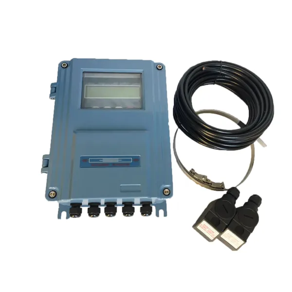
 DN1000 Insertion Type Ultrasonic Flow Meter for Clean Water Pure WaterNegotiableMOQ: 100 Sets
 -
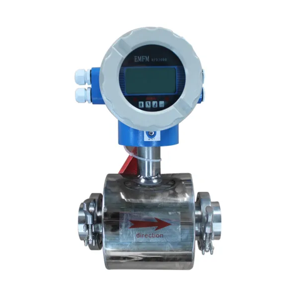
Advanced Electromagnetic Flowmeter With Integrated Liquid Measurement TechnologyNegotiableMOQ: 10 Units
-
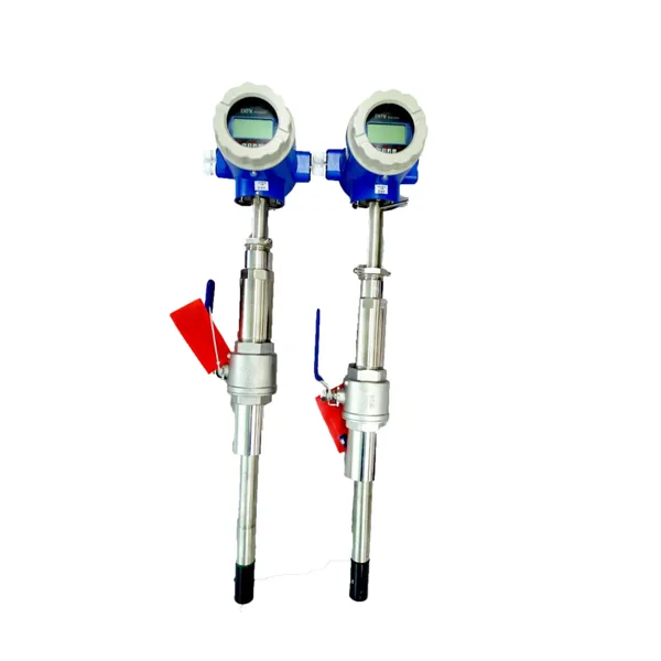
High Precision Electromagnetic Flow Meter for Southeast Asia Export - Easy Installation & Reliable After-SaleNegotiableMOQ: 10 Units
-
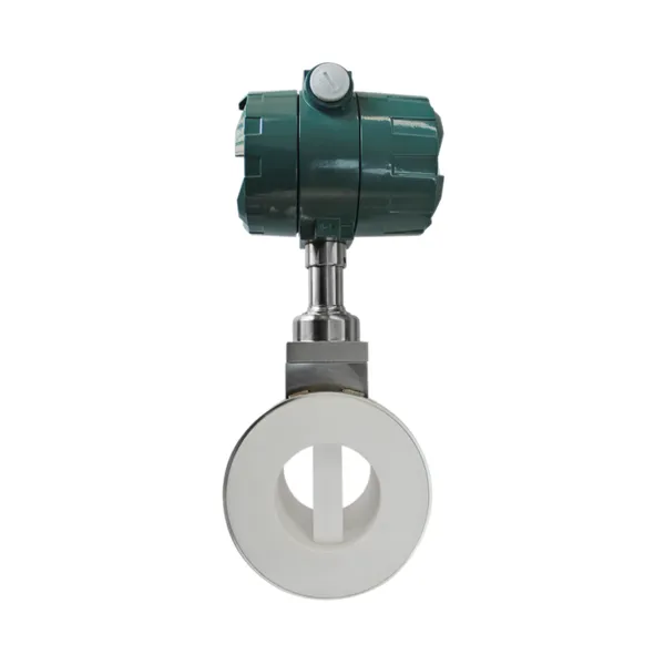
Advanced Digital Vortex Flow Meter for Accurate Water and Liquid MeasurementNegotiableMOQ: 10 Pieces
-
DN50 304 Stainless Steel Turbine Flowmeter for Diesel Oil MeasurementNegotiableMOQ: 10 Units
-
Low-Temperature Turbine Flowmeter for Liquid Nitrogen Applications in Cryogenic SystemsNegotiableMOQ: 10 Units
-
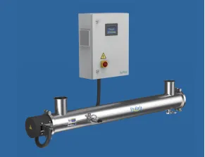
Industrial UV Disinfection Machine for Food & Beverage Industry - UVTunnelTM Tech, 1-40℃ Working TempNegotiableMOQ: 1 Set
-
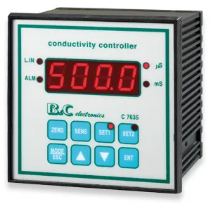
C 7635 High-purity Water Conductivity Transmitter With Automatic Temperature Compensation 0-100°CNegotiableMOQ: 1 Set
-
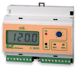
C 3655 Conductivity Meter Output Conductivity Transmitter With IP65 Waterproof HousingNegotiableMOQ: 1 Set
-
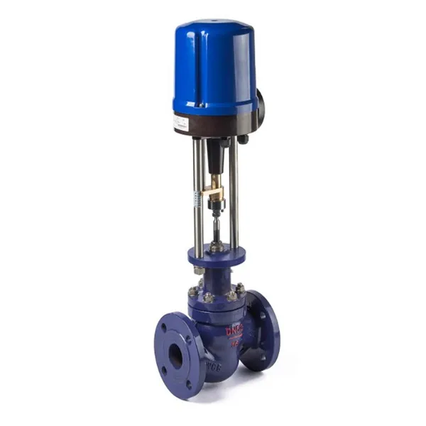
High Performance Electric Regulating Valve for Environmental Protection Water Treatment SystemsNegotiableMOQ: 1 Piece
-
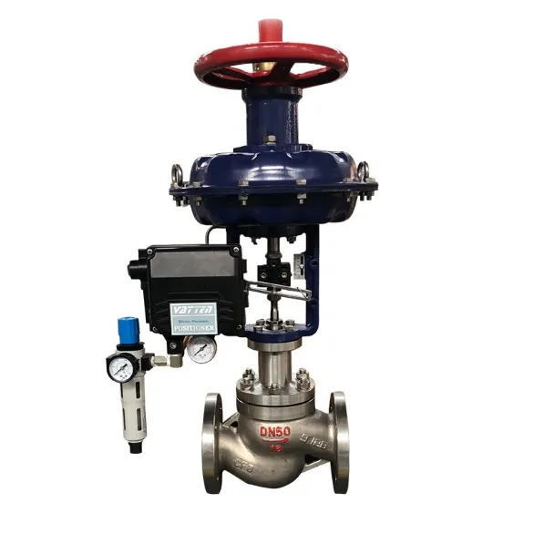
High Quality Pneumatic Control Valve for Chemical Pharmaceutical Industry Chinese Strong Factory With Spot StockNegotiableMOQ: 1 Piece
-
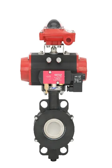
Pneumatic or Electric Actuator Compatible Full Fluorine-Lined Butterfly Valve With On/Off and Smart Regulating OptionsNegotiableMOQ: 1 Set
-
Powder Conveying Specialized Pneumatic Y-Type Ball Valve, Full Bore Design With No Dead Space for Clean MediaNegotiableMOQ: 1 Set
-
Manual, Pneumatic, or Electric Flanged Ball Valve With ISO5211 High Platform, Easy 90-Degree Operation for Fluid ControlNegotiableMOQ: 1 Set
-
Zero Leakage Full Fluorine-Lined Butterfly Valve Featuring Superior Corrosion Resistance and Long Service LifeNegotiableMOQ: 1 Set
-
Bottom Discharge Valve VTF-88-3 Series, DN25-DN300, Stainless Steel 316L/Carbon Steel, PN10/PN16 Class 150, Manual or Pneumatic ActuationNegotiableMOQ: 1 Set
-
Cost-Effective Knife Gate Valve With Rigid/Elastic Gate Options - Ensures Tight Shutoff and High Performance in Diverse Industrial SettingsNegotiableMOQ: 1 Set
-
FLS PH/ORP 200 Epoxy Resin Body Glass Bulb Electrode (Single-Junction/Double-Junction Versions)NegotiableMOQ: 100 Pieces
-
FLS F3.20 Flow Sensor Optimized for HVAC Systems, Cooling Units, and Boiler Feed Water, Featuring Low Maintenance and High Precision AccuracyNegotiableMOQ: 100 Pieces
-
FLS F3.80 Oval Gear Flow Sensor – High Precision for High-Viscosity Liquids (10-150L/h, IP65)NegotiableMOQ: 100 Pieces